Battery Type/'s
-Lithum 100AH 3.3KW Charger-Lithum 200AH 3.3KW Charger
-Lithum 100AH 6.6KW Charger
-Lithum 200AH 3.3KW Charger
Below are the steps to take for testing the lithium cells with diagnostic tool. This is typically done when you have an issue with no fault codes. Possible symptoms would be low power, low range or shutdown issue while operating vehicle. If you do have faults you want to check over them first, then if no solution, perform this test.
This requires lithium diagnostic tool U5665A-N along with your own laptop. If you do not already have the program installed on your laptop/computer, need a refresh on what program is needed or how to connect to the vehicle see these instructions.
Open Orion BMS Utility program for the version of BMS your vehicle is equipped with.
 Click on connect to BMS
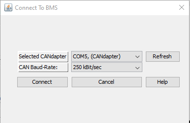 Selected CAN adapter should have COM#
CAN Baud-Rate make sure 250 kBit/sec is selected
Click on connect
Note: Vehicle needs to be power up on its own or plugged in at the front bumper. Key does not need to be on to connect.
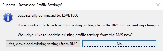
If connection was successful, you will get this window, click No.
In the main screen across the top are tabs. Click on "Live Cell Data"
In the lower right of the live cell data tab, you will find this button  Click on it.
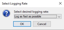
Typically, by default "Log as fast as possible" is selected. Fast is better for accuracy. But file size gets larger. Most cases this is fine. Click OK
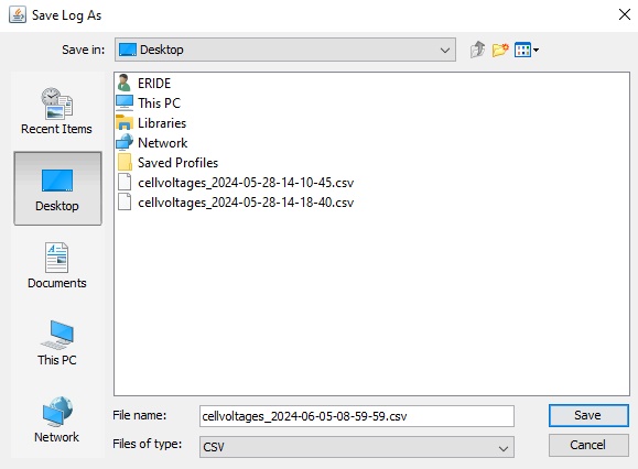
Here you get your typical windows popup asking where to save this file. Typically, just on your desktop is fine unless you have a specific location you want to place it. The file name can be changed if you wish. By default, it is a date-time format. Click Save.
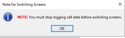
You will get this notification just stating you will not be able to switch tabs when this is running. Click OK.
At this point the program is recording vehicle information. At this point you will want to operate the vehicle. Remember the longer you drive it the bigger the file gets. Typically for this test just start and stop three times. With each start do a full acceleration and with each stop come to a complete stop.
In the lower right of the live cell data tab, you will find this button  Click on it.
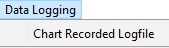
In the upper left corner of program, you will find "Data Logging" Click on it which will drop down and then select "Chart Recorded Logfile".
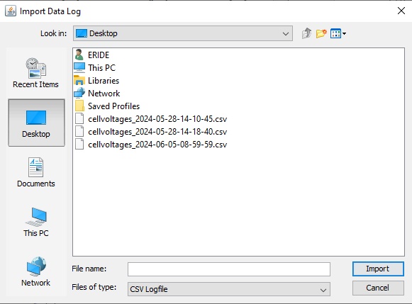
Here you get your typical windows popup asking what file to load. You will need to find the location you saved the file at. In this example I saved it to my desktop and file saved was "cellvoltages_2024-06-05-08-59-59.csv" Click on the saved file and then click on Import.
The file will load. Depending on file size and computer speed will vary how long it takes to load. Typically, less then 30 seconds.
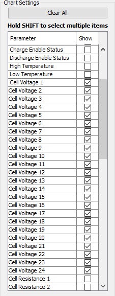
After loading you will get a screen with this chart on the left side. Check mark Cell Voltage 1 and you will see the black box on the right create a line. This line represents the cell voltage of cell# 1 during the test. Now take and checkmark cell voltage 1 thru 24.
The graph on the right will fill in with all the cell voltages during the test. Looking something like this.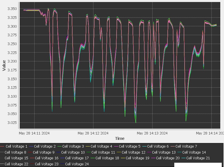
What you are looking for are lines that expand out from the rest of the cells. In this example shown all cells are good and battery pack is balanced. All 24 cell voltages are together. If you have one cell or multiple ones that are deviating from the rest if you place your mouse courser right at the point of one of the lines, it will display which cell it is and the voltage reading at that point.
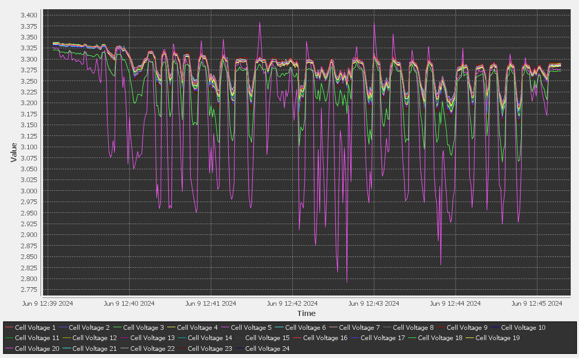
Below is an example which has two cells in question. In this case cell #5 is the violet line. This cell is dropping a lot lower in voltage under a load, and you can see it spike high during the regen / recharging. Also, cell #3 the green line is starting to show signs of having an issue.
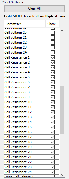
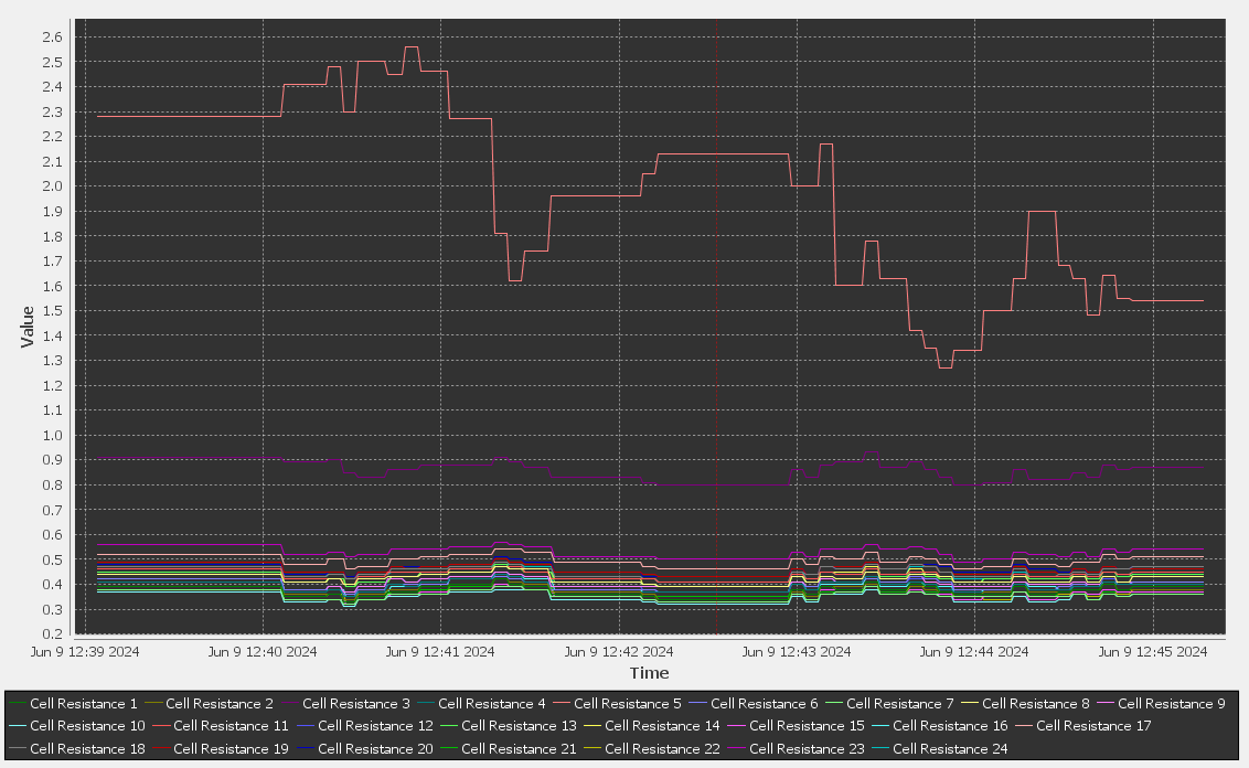
Another helpful graph to show is the resistance. Click on Clear All too clear all checkmarks. Then checkmark Cell Resistance 1thru 24.
The graph on the right will fill in with all the cell resistance during the test. Looking something like this.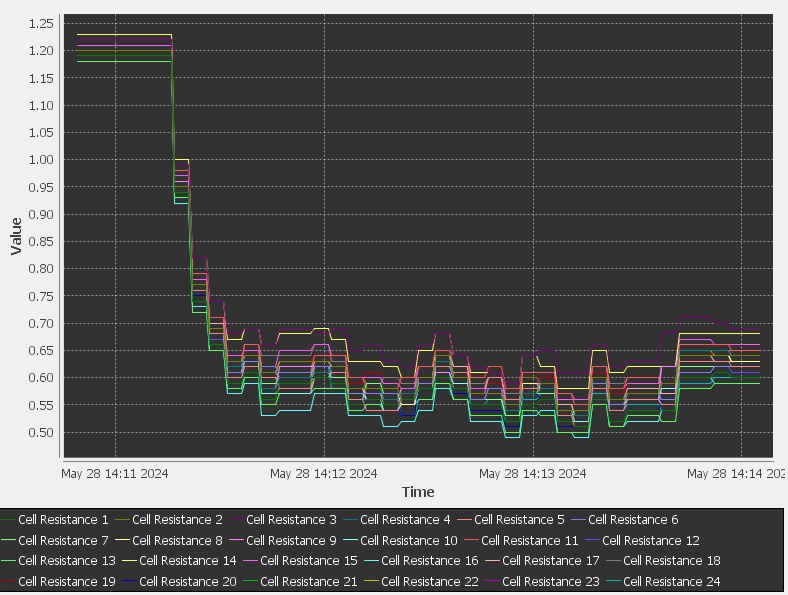
This represented graph started high due to resistance not being calculated yet. It takes voltage drop and current increase for resistance to get calculated. Any resistance readings above 1.5 for 100AH pack or .75 for 200AH pack at 70 deg. F cell temp are possible cells with an issue. One variation to this is if the cells are cold, they will have higher resistance. So again, you are looking for cells that stand out. If all cells have high resistance, then the entire pack is towards its end of life and may need to be replaced.
Below is an example of a 200AH pack which has two cells in question. In this case cell #5 is the orange line. This cell is having high resistance. Also, cell #3 the violet line is starting to show signs of having an issue in comparison to the remaining good cells. And this is the 200AH pack so any resistance readings above .75 at 70 deg. F are considered high resistance.
So, some things to note. You can see other useful information in this logged data such as: State of charge, pack voltage, pack current, pack CCL (Charge current limit), pack DCL (discharge current limit), High and low temperature among other things. Use any of these readings to understand the battery pack or single lithium cell issue.
If you have a cell reading that is incorrect you need to first, make sure the connection between the BMS and that cell is good. The BMS is wired to each cell. If one of these wires is loose creating a bad connection the reading will be wrong. You can also double check the cell voltage readings between the BMS and the cell itself by hooking up a voltmeter to the cell in question. Create a load and compare the readings between your voltmeter and the BMS reading. If readings are the same more than likely the BMS is reading correct voltage, and the cell is bad. Which you need to evaluate age of pack and how the other cells tested to make the discission whether the single cell can be replaced, or the entire pack needs replacement. When replacing single cells balancing is something that needs to be considered as well. New cells are at about 60% state of charge. Creating an imbalanced pack will compound the issue.
Cell #1 is the driver's side rear cell or the most negative cell. Cell #24 is the passenger's side rear most positive cell. Note 200AH battery packs have 48 cells. Each cell# consists of 2 cells wired in parallel. So, cell #1 is still the driver's side rear cell but is also the second cell. Cell #2 is the 3rd and 4th cell in the pack. And so on.
For lithium cell replacement see: 100AH or 200AH