Year - Model
2025 - EXV42025 - EXV2
2024 - EXV4
2024 - EXV2
2023 - EXV4
2023 - EXV2
2022 - EXV4
2022 - EXV2
2021 - EXV4
2021 - EXV2
2020 - EXV4
2020 - EXV2
2019 - EXV4
2019 - EXV2
2018 - EXV4
2018 - EXV2
2017 - EXV4
2017 - EXV2
2016 - EXV4
2016 - EXV2
2015 - EXV4
2015 - EXV2
2014 - EXV4
2014 - EXV2
Drive System/'s
ALL DrivesBattery Type/'s
-Lithium 100AH Batteries with 3.3KW Charger-Lithium 200AH Batteries with 3.3KW Charger
-Lithium 100AH Batteries with 6.6KW Charger
-Lithium 200AH Batteries with 6.6KW Charger
-Lithium 110AH Batteries with 3.3KW Charger
-Lithium 110AH Batteries with 6.6KW Charger
HVAC System/'s
All HVACManufacture Dates
Between 03/11/2014 Thru 12/31/2025
Lithium Battery Warmer Circuit Diagram
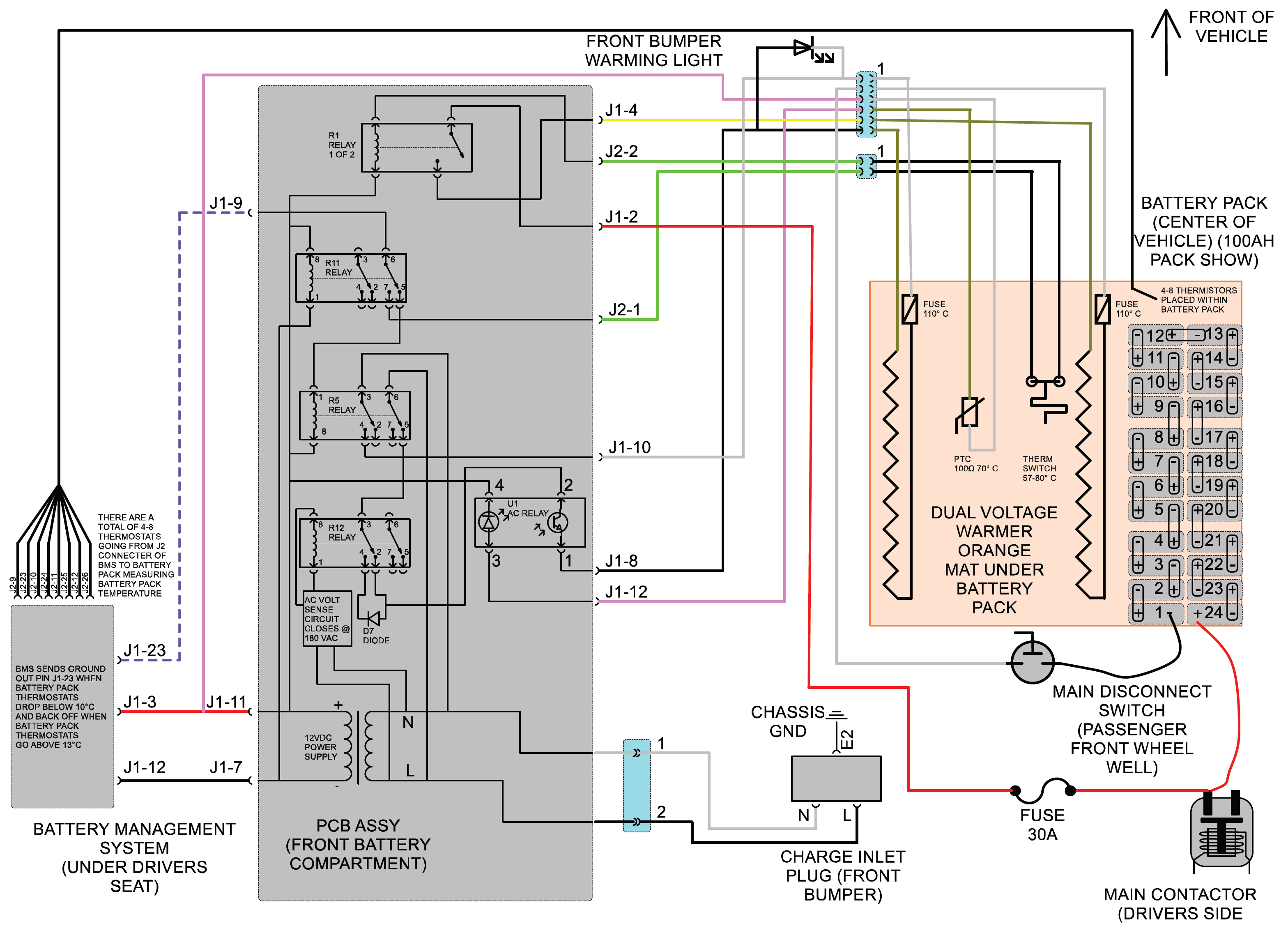
A few things to note here.
- The warmer is two elements. One side of the element is powered by AC voltage while vehicle is plugged in, and the other side is powered by DC voltage for when vehicle is not plugged in.
- The warmer operates the same on both 120VAC and 220VAC due to a voltage sensing circuit. A diode is added to the AC warmer circuit when plugged into voltages above 180VAC cutting the sine wave in half.
- The BMS (battery management system) senses battery pack temperature with 4 thermostats on the 100, 110 & 150AH packs and 8 thermostats on the 200AH pack. When the lowest of the 4 thermostat reaches 10° C the BMS supplies ground out J1-23. When the lowest thermostat reaches 13° C J1-23 turns off. To override this for testing purposes you can jumper J1-12 to J1-23 at the BMS connector. BMS should remain plugged in. But note when doing this the warmer will remain on increasing battery pack temperature. Make sure to not do this for extended periods of time.
- Circuit shown in PCB ASSY is for reference only to understand how the circuit is wired. It is not serviceable.
- The tests are note in a particular order.
You will want to determine which of the warming systems is not operational. This can be done a number of ways. Easiest way is to trigger the warming system to turn on either by having vehicle in cold ambient temps or jumper J1-12 to J1-23 at the BMS connector.
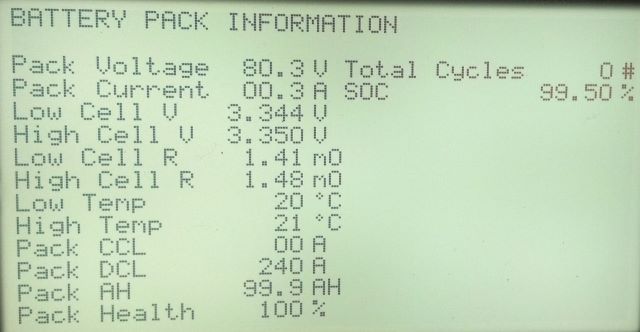
- If vehicle will turn on you can press and hold the up button of the dash display until the second screen comes up showing battery pack information. As shown in the next image. This can provide warmer information such as DC current draw and high and low battery temperature readings. If temperature readings do not match current conditions or vary greatly one of the thermistors may be bad or the BMS may have an internal issue. This would need further diagnostics requiring the lithium BMS diagnostic tool as described in this forum.
- To test the AC side of the warmer.
- Turn main battery disconnect switch off in right front wheel well.
- Plug vehicle in at front bumper to say 120VAC.
- Use an AC current clamp/meter over the black wire coming out of the back of the inlet plug or an in-line current meter. You should measure roughly 1.8 amps for 100AH, 110AH or 150AH battery packs or 3.6 amps for the 200AH battery pack.
- To Test the DC side of the warmer.
- Vehicle must be operational. Then turn the ignition key on.
- Press and hold the up button of the dash display until the second screen comes up showing battery pack information. As shown in the image above.
- In the case of this image the warmer is not on. But if it was the pack current would read 3 amps for 100AH, 110AH or 150AH battery packs or 6 amps for the 200AH battery pack. Also, here you will see the high and low battery pack temperature.
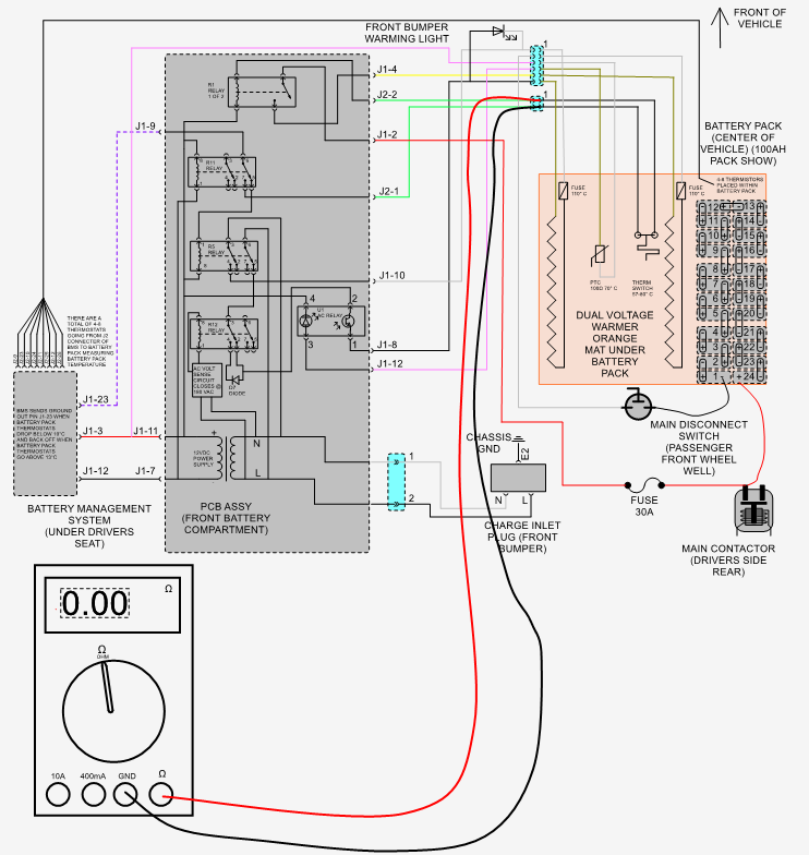
Diagnostics of DC side of warmer
Test #1
To test the DC warmer, unplug the battery warmer at the 6-pin connector. At the warmer side ohm test between pin# 2 & 5 of warmer 6 pin connector. If you measure roughly 27Ω continue to test #1-1. If not you either have a bad connection, bad thermal fuse or element in warmer is bad. Thermal fuse is part# U5669A-1N.
Test #1-1
Take and measure the vehicles side if the 6-pin connector and you should read pack voltage (typically 80VDC) If so, warmer should be operational. Else if not continue to test #2.

Test #2
To test the DC thermal switch, unplug the 2-pin connector of the battery warmer. On the warmer side of the connector ohm test between pin's 1 & 2. Should measure a closed circuit, if so continue to test #2-1. If circuit is open thermal switch may bad and needs to be replaced. Part# of thermal switch is U5732A-N.
Test #2-1
Take and jumper the two terminals together of the 2-pin connector on the vehicle side. You should hear a relay close inside the lithium PCB assembly. Also, if the 6-pin warmer connector is plugged back in the warmer should start to operate. Can be seen by looking at the pack current in the dash display. If it does not still operate more than likely the PCB assembly needs to be replaced. If it does, then you still have a bad thermal switch, and it should be replaced.
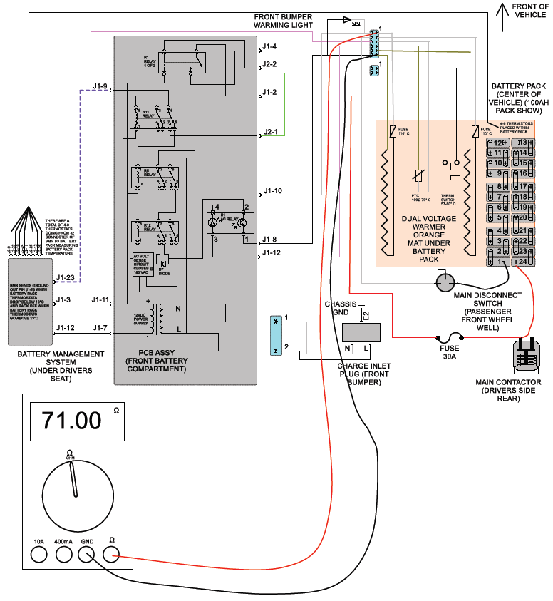
Diagnostics of AC side of warmer
TEST #3
To test the AC warmer, unplug the battery warmer at the 6-pin connector. ohm test between pin# 1 & 6 of warmer 6 pin connector. If you measure roughly 71Ω continue to test 3-1. If not you either have a bad connection, bad thermal fuse or element in warmer is bad. Thermal fuse is part# U5669A-1N.
Test #3-1
Take and measure the vehicles side of the 6-pin connector and you should read same voltage as you are plugged into (example 120VAC) if not you either have a wiring connection issue or the PCB assembly is bad and needs to be replaced.
Test #4
At the 6-pin connector. ohm test between pin# 3 & 4 of warmer 6 pin connector. If you measure roughly 100Ω @ 70° C, then you may have a bad lithium PCB assembly. If not, you could have a bad thermistor which is part# U5733A-N.
