Drive System/'s
ALL DrivesBattery Type/'s
-Flooded Lead Acid,HVAC System/'s
All HVACManufacture Dates
Between 01/01/2005 Thru 01/12/2010
Charger Safety Warnings
1. Charge
only rechargeable batteries. Other types
of batteries may burst causing personal injury and damage.
2. If
either end of your charger plug becomes damaged in any way, make sure to
replace it IMMEDIATELY.
3. Use
of an attachment not recommended or sold by the vehicle manufacturer may result
in the risk of fire, electrical shock, or injury to persons.
4. Do
not operate the charger if it has received a sharp blow, been dropped, or
otherwise damaged in any way; take it to a qualified service center.
5. To
reduce the risk of electrical shock, unplug the charger from a live outlet or
disconnect AC power to the outlet before attempting any maintenance or
cleaning. Turning off controls will not reduce the risk of electric shock.
6. DO
NOT use jumper cables to the batteries on this vehicle.
7. Only
charge this vehicle with the appropriate battery charger that is supplied with
the vehicle.
8. Lead
acid batteries generate gases which can be explosive. Charge the batteries only in well ventilated
areas.
9. Do
not disconnect charger DC output terminals from battery when charger is
on. The resulting arching and burning
will damage the connectors and could cause the battery to explode.
10. Keep
sparks, flame, and smoking materials away from battery.
11. Do not
leave charger connected while unattended for more than two consecutive
days. Severe overcharging and possible
damage to batteries will result if charger should fail to turn off.
12. Never plug
in both 120 volt and 220 volt cords at the same time. When one cord is plugged
into one receptacle the other receptacle has live power also.
13. Never
charge a frozen battery.
14. Do not lift a battery by the terminal posts, or internal damage may result.
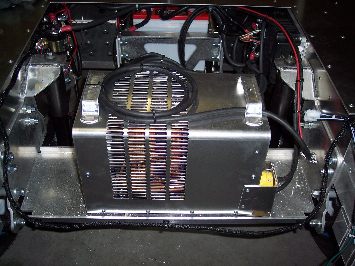
Charger Operation
The battery charger is a self-regulating charger with a minimum of moving parts, designed for long, trouble free service. The charger utilizes convection cooling which maximizes the reliability and minimizes any maintenance costs. Charge only flooded, liquid electrolyte (wet) lead acid batteries with this charger.
Normal charging at the finish
charge rate for the last three to five (3-5) hours is important to achieve
equalization of all battery cells every time the batteries are charged. New batteries or batteries charged in cold
temperatures (below 50 degrees F) will require more time to achieve full
charge.
Charge time will vary depending on the depth of discharge. Allow 8 hours for normal charging. Fully discharged batteries may require up to 12 hours to be properly charged and equalized.
Charging Procedure
1. Connect
the AC supply cord to the correct single phase outlet, located in the front
bumper of the vehicle, with one of the proper voltages and frequencies as
follows:
-115 volts 16 amp 60 hertz
-230 volts 13 amp 60 hertz
2. The
charger will start after a short delay as indicated by the transformer hum and the ammeter movement.
3. Once the charge is completed the charger will turn off automatically. After the charger has turned off, disconnect the AC supply cord from the outlet.
Charging
1. Turn
the ignition switch off and set the parking brake.
2. If
the battery pack voltage is reading below 34 volts the charger will not turn
on. The charger relay will have to be
by-passed in order for the charger to turn on.
3. Disconnect
the DC cords from the vehicle.
4. Disconnect
both AC cords from the charger’s electrical outlets.
5. Remove
the 10 screws securing the charger cover and remove the cover from the charger.
6. Follow
instructions listed below depending on which voltage you are using to charge
the vehicle. Make note of the wires’
original positions, so they can be put back when the procedure is complete.
7. Plug
the DC cords into the charger receptacle first and then plug the AC cord into
the electrical outlet.
8. The
charger should turn on and begin to charge the batteries. Allow the charger to operate for one to two
hours, but not more than two hours.
9. After
one to two hours, disconnect the charger AC cord from the electrical outlet
first. Then, disconnect the DC cords
from the charger.
10. Change the
wires inside the charger back to their original location.
11. Re-install
the charger cover and the 10 screws securing the cover.
12. Connect the
DC cords to the charger first and then plug the AC cord into the electrical
outlet.
13. The charger
should turn on and begin to charge the batteries. Allow the charger to operate until the charger
shuts off automatically.
14. When the charge cycle is complete, test the batteries again. If the battery pack voltage is above 34 volts and the vehicle will not operate, it will be necessary to troubleshoot the vehicle’s electrical system to determine which electrical component has failed.
·
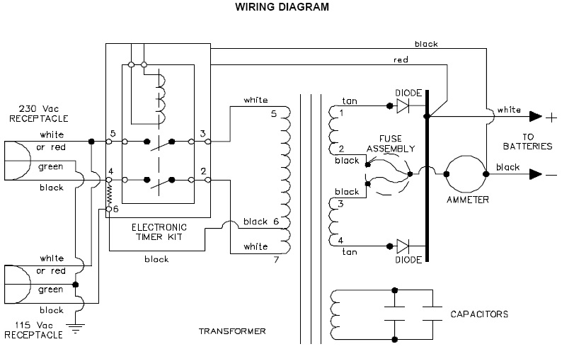
115 volt
charging (See diagram)
I.
Inside the charger locate the black wire that is going
to terminal location #6 of the circuit board.
II.
Unplug this black wire and plug it into terminal
location #3 of the circuit board.
III.
Locate the white wire going to terminal location #5 of
the circuit board.
IV.
Unplug this white wire and plug it into terminal
location #2 of the circuit board.
·
220 volt
charging (See attached diagram)
I.
Inside the charger locate the black wire that is going
to terminal location #4 of the circuit board.
II.
Unplug this black wire and plug it into terminal
location #3 of the circuit board.
III.
Locate the white wire going to terminal location #5 of
the circuit board.
IV. Unplug this white wire and plug it into terminal location #2 of the circuit board.
Charger Troubleshooting Guide
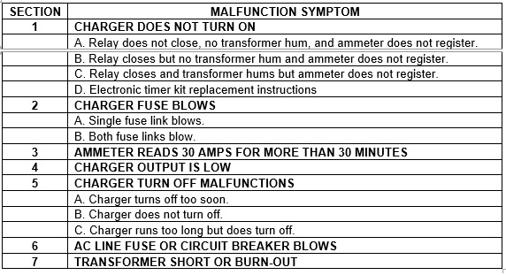
SECTION 1 – CHARGER
DOES NOT TURN ON
In normal operation, the charger DC output connector must be connected to the batteries in order to turn the charger on. A time delay of two to five (2-5) seconds is provided to allow adequate time to make a secure connection before the charger turns on. After this time delay, the power relay closes and an audible "click" should be heard. When the relay closes, AC power is supplied to the transformer primary coil. If operating properly, the transformer should hum and the ammeter should indicate the charge rate. If the charger does not turn on properly, refer to Part A, B or C for specific test procedures.
Part A Relay does not
close, no transformer hum, and ammeter does not register
Check
to be sure the power supply cord is securely connected to a live outlet. Check
the DC output connector and the battery connector for damage, dirt or corrosion
that would prevent a good electrical connection.
WARNING:
IF THE PLUG OR RECEPTACLE IS BROKEN, TWISTED, BENT OR LOOSE AND DOES NOT MAKE
GOOD ELECTRICAL CONTACT, HAVE IT REPLACED BY A QUALIFIED SERVICE AGENT
IMMEDIATELY. DO NOT USE THE CHARGER IN THIS CONDITION AS FIRE OR PERSONAL
INJURY CAN RESULT.
Then
disconnect the power supply cord from its outlet. With the DC output
connector still connected to the battery connector, measure the voltage
at the battery connector using a suitable DC voltmeter. The
voltage reading should be the same as the battery terminal voltage and
must be 70% of the nominal rating of the battery pack. Example: 24VDC
batteries need at least 16.8 VDC. If the DC voltage is within the
above limits, remove the charger cover and verify that the charger is
properly wired and you read the same voltage (24 to 50 VDC) inside the
charger where the WHITE and BLACK wires of the DC cord attach. If
the battery DC voltage measured inside the charger is now below the
above limits or not present, the DC plug or cordset has an internal break
and must be replaced. If the charger is wired correctly and a
satisfactory battery DC voltage is measured inside the charger, a
malfunction in the Electronic Timer Kit has probably occurred. Due to
its complexity, do not attempt to make field repairs to any part of
the Electronic Timer Kit. If a malfunction exists, simply remove the
entire Electronic Timer Kit and replace it with a new one. Refer to Part
D, "Electronic Timer Kit Replacement", for correct procedure.
The Electronic Timer Kit may be bypassed in order to verify that a
malfunction exists. First disconnect the charger power supply cord from
its outlet and the DC output connector form the battery connector. Place
a jumper wire between terminals #1 and #3 to bypass the Electronic Timer
Kit as shown in Figures 1 and 2. The power supply cord is now
connected directly to the primary transformer coil and the transformer
should hum when the power supply cord is connected to a live outlet.
The charger operation may be checked by first connecting the DC output
connector to the battery connector, and then connecting the power
supply cord to an outlet. If normal charging current is indicated on the
ammeter, the Electronic Timer Kit is defective and must be replaced.
CAUTION:
DO NOT CHARGE BATTERIES WITH THE ELECTRONIC TIMER KIT BYPASSED. THE CHARGER
WILL REMAIN ON AS LONG AS THE POWER SUPPLY CORD IS CONNECTED TO AN OUTLET.
SEVERE OVERCHARGING AND EVENTUAL DAMAGE TO BATTERIES WILL RESULT.
If the transformer does not hum and the ammeter still does not register with the Electronic Timer Kit bypassed, a continuity check of the charger AC circuit is necessary. Disconnect the power supply cord from its outlet and the DC output connector from the battery connector and, with a suitable continuity tester, check the circuit across the power supply cord prongs. With the Electronic Timer Kit bypassed, the CIRCUIT SHOULD BE COMPLETE. If the circuit is not complete, individually check the continuity of the power supply cord, primary transformer coil and all connections.
Part B Relay closes,
but no transformer hum, and ammeter does not register
Check
to be sure the power supply cord is securely connected to a live AC outlet.
When three-prong to two-prong adapters are used, they tend to work loose,
resulting in a poor connection. Check the AC line fuse or circuit breaker and,
if possible, measure the AC line voltage at the outlet to be sure AC power is
present. If necessary, connect a functioning charger, utility light, or other
electrical appliance to the outlet to verify the presence of AC power. If AC
power is present, disconnect the power supply cord from its outlet and the DC
output connector from the battery connector. Bypass the Electronic Timer Kit as
described in Section 1, Part A, and with a suitable continuity tester, check
the circuit across the power supply cord prongs. With the Electronic Timer Kit
bypassed, the CIRCUIT SHOULD BE COMPLETE. If the circuit is complete, refer to
the Wiring Diagram and check the relay wiring and all connections. If the
circuit is not complete, check the wiring of the power supply cord, transformer
primary coil leads, and the Electronic Timer Kit. If the charger is wired
correctly, individually check the continuity of the power supply cord,
transformer primary and relay.
Part C Relay closes,
and transformer hums, but ammeter does not register
If
the relay closes and the transformer hums, the charger AC circuit and
Electronic Timer Kit are functioning properly. If the ammeter does not
register, a fault in the charger DC circuit exists and a continuity
check must be performed. Disconnect the power supply cord from its
outlet and the DC output connector from the battery connector, and check
the charger fuse. If a fuse link is blown, refer to Section 2,
"Charger Fuse Blows", for further tests. If the fuse checks
good, use a low voltage continuity tester to perform the following
tests:
1. Connect the tester
leads to the charger DC output connector and note the readings. Reverse
the tester leads and check the output connector again. The circuit
should be complete in only one direction. If the circuit does not conduct
in either direction and the fuse is good, individually check the
continuity of the DC output cord, ammeter, diodes, and all connections.
If the circuit conducts in both directions, a "short" exists
in the charger DC circuit. First check the DC output cord for a
"short" between the two wires. It is more likely that one or
both diodes have "shorted". Refer to Section 2, "Charger
Fuse Blows", for continuity test of diodes.
2.
If
the charger DC circuit test is good, a check of the capacitor is necessary.
Disconnect the power supply cord from its outlet and the DC output connector
from the battery connector.
Then disconnect both transformer coil leads from the capacitor terminals. Use care when disconnecting the capacitor leads so the wires do not break. Using an ohmmeter, set the scale to R x 10K ohms and test the capacitor as follows:
· GOOD CAPACITOR When the ohmmeter leads are connected to the capacitor terminals, the meter needle jumps to mid-scale and rapidly moves to higher resistance (:)
· OPEN CAPACITOR When the ohmmeter leads are connected to the capacitor terminals, the meter needle does not move and stays at high resistance (:). A bulge in the top of the capacitor may be visible if the capacitor has failed "Open".
·
SHORTED CAPACITOR When the ohmmeter leads are connected to the
capacitor terminals, the meter needle jumps immediately to zero ohms and remains
there. If
the capacitor is "Open" or "Shorted", it must be replaced.
CAUTION:
USE ONLY THE PROPERLY RATED CAPACITOR FOR REPLACEMENT. THE USE OF A DIFFERENT
VALUE CAPACITOR MAY RESULT IN IMPROPER CHARGING, CAPACITOR FAILURE, TRANSFORMER
BURN-OUT, AND/OR
3.
If
the charger DC circuit and capacitor check good, a test of the transformer is
necessary. Refer to Section 7, "Transformer Short or Burnout" for
test procedures.
Part D Electronic Timer
Kit replacement
The
Electronic Timer Kit should always be replaced as a complete assembly. The
tools required are a Phillips head screwdriver, 3/8" and 11/32"
wrenches, and pliers. No soldering is required. To replace the kit, follow the
step-by-step procedures listed below.
1.
Disconnect
the charger power supply cord from its outlet and the DC output connector from
the battery connector, and remove the charger cover.
2.
Disconnect
the GREEN (if included), BLACK and RED wires of the Electronic Timer Kit. Then remove
the BLACK and WHITE leads of the power supply cord and both primary transformer
coil leads from the Electronic Timer Kit terminal tabs. The Kit can be removed
by removing the three mounting screws on the charger front panel. Save all
hardware for reassembly.
3.
Install
the replacement Electronic Timer Kit by reversing the disassembly procedures
described in Step 2. When reconnecting the wires to the Electronic Timer Kit
terminal tabs, support the terminal board to prevent damage to the electronic
circuit board. Connect either transformer primary lead to terminal #2, and the remaining
primary lead to terminal #3. Connect the BLACK lead of the power supply cord to
terminal #1 on the Electronic Timer Kit and the WHITE lead of the power supply
cord to terminal #2. Connect the RED wire of the Electronic Timer Kit along
with the WHITE or RED lead of the DC cord to the Heatsink Assembly. Connect the
BLACK wire of the Electronic Timer Kit along with the BLACK lead of the DC cord
to the ammeter post. Do not allow the ammeter post to turn when tightening the
nut. Reconnect the GREEN wire of the Electronic Timer Kit along with the
transformer secondary lead to the diode lead terminal (if included).
CAUTION:
BE SURE ALL CONNECTIONS ARE CLEAN AND TIGHT. ALSO CHECK TO BE SURE ALL WIRES
AND TERMINALS ARE POSITIONED SO THEY DO NOT SHORT TOGETHER OR TO THE CHARGER
CASE.
4.
Replace
the charger cover and check the Electronic Timer Kit for proper operation as follows:
a.
With
the DC output connector disconnected from the battery connector, insert the
power supply cord into an outlet. The relay on the Electronic Timer Kit should
not close. A DC voltmeter connected across the DC output connector should
indicate zero volts.
b.
Disconnect
the power supply cord from its outlet and connect the DC output connector to
the battery connector. The relay on the Electronic Timer Kit should close with
an audible "click" after a two to five (2-5) second delay.
c.
If
the Electronic Timer Kit does not operate as (a) and (b) above, refer to the
wiring diagram and check to be sure the charger is wired correctly. If the
Electronic Timer Kit operates properly, the charger is ready for use. Always
monitor the first charge cycle to verify that the charger is turning off
properly.
SECTION 2 – CHARGER
FUSE BLOWS
The
charger fuse assembly consists of a dual element fuse link under a transparent
cover mounted on the charger front panel. Each fuse element is electrically
connected in series with a rectifier diode to provide protection for the transformer
in the event of a diode failure. Visually inspect and electrically test the
fuse to determine if one or both fuse links are blown and refer to Part A or
Part B for test procedures. Locate and correct cause of trouble
before replacing blown fuse. DO NOT attempt to repair the fuse link as inadequate
protection will result.
Part A Single fuse link
blows
This
condition is normally caused by a short circuit failure of one diode. The fuse
link will blow when the charger DC output connector is connected to the battery
connector, regardless of whether the power supply cord is connected to an
outlet. To check the diodes, disconnect the power supply cord from its outlet
and the DC output connector from the battery connector, and then disconnect one
transformer secondary coil lead from the diode terminal. Using a low voltage
continuity tester, connect one tester lead to the diode mounting plate and the
other tester lead to a diode terminal. Note the reading, then reverse the tester
leads, and check each diode again. If a diode conducts current in both
directions, it is "shorted" and the complete Heatsink Assembly with
Diodes must be replaced.
Part B Both fuse links
blow
This
is normally caused by a reverse polarity connection between the charger DC
output connector and the battery connector. Check the battery pack and battery
connector to be sure they are wired in the correct polarity. If possible, check
the voltage and polarity at the battery connector with a DC voltmeter. Also,
check the charger DC output connector for the correct polarity. The WHITE or RED
wire should be connected to the positive (+) contact, and the BLACK wire to the
negative (-) contact. If a reverse polarity connection is made between the
charger and batteries, both fuse links will blow regardless of whether the
power supply cord is connected to an outlet.
SECTION 3 – AMMETER
READS 30 AMPS FOR MORE THAN 30 MINUTES
This
high output condition is caused by misuse, connecting the charger to an
incorrect battery system which is lower than what is rated for the charger. A
common error is to install one or more of the batteries in a battery pack
reverse polarity. Using a suitable DC voltmeter, test to be sure all batteries
in a battery pack are correctly wired, and also test the battery pack voltage
at the charging connector. After charging for 30 minutes at this excessive
rate, the measured on-charge voltage should rise to 34 to 38 volts DC for a
36-volt system. While charging, voltage measurements lower than this indicate
an incorrect or failed battery pack that must be corrected before using the
charger.
CAUTION:
DO NOT CONNECT THE CHARGER TO
SECTION 4 – CHARGER
OUTPUT IS LOW
The
most probable cause of low output is a single fuse link blowing as a result of
a short circuit failure of one diode. Refer to Section 2, "Charger Fuse Blows",
for troubleshooting procedures. On rare occasions, a short circuit failure of
the transformer coils may cause the output to be low. Refer to Section 7,
"Transformer Short or Burn-out", for test procedures. Another failure
that could cause low output is an open diode on the heatsink assembly. To check
for an open diode, follow the procedures in “Section 2 – CHARGER FUSE BLOWS,
Part A Single fuse link blows” and test the continuity of both diodes. An open
diode will not have continuity in either direction.
CAUTION:
DO NOT USE THE CHARGER IF THE OUTPUT IS LOW. BATTERIES WILL NOT REACH FULL
CHARGE, THEREBY INCREASING THE POSSIBILITY OF A HARMFUL DEEP DISCHARGE DURING
THEIR NEXT USE.
SECTION 5 – CHARGER
TURN-OFF MALFUNCTIONS
The
Electronic Timer Kit turns the charger off as well as on. Proper charge time is
determined by many factors, but the main elements are: (1) battery size, (2)
depth of battery discharge, and (3) finish charge rate. Large, severely
discharged batteries require more time to reach full charge than do smaller, lightly
discharged batteries. The charge rate, as indiated by current flow in amperes
on the panel meter, is controlled by the batteries' rising voltage during
charge. The higher the on-charge voltage will rise, the lower the finish charge
will be before the Electronic Timer terminates charging.
THE
FOLLOWING TIMER MALFUNCTIONS ARE OCCASIONALLY DUE TO FACTORS OTHER THAN THE
CHARGER'S PERFORMANCE. TO HELP ISOLATE THE PROBLEM, IT IS OFTEN NECESSARY TO
USE THE CHARGER ON A DIFFERENT SET OF BATTERIES AND THE ORIGINAL SET OF
BATTERIES ON ANOTHER CHARGER.
Part A Charger turns
off too soon
Check
to be sure the power supply cord is securely connected to a live outlet. If the
power supply outlet is live, proceed with the next step. To determine if the
charger did shut off too soon, disconnect and reconnect the charger DC output connector.
This will restart the charger. Observe charger output on the ammeter.
1.
The
ammeter needle jumps smartly to between 20 and 25 amps and then tapers below 14
amps within 15 minutes. This indicates that the batteries were truly charged.
The apparent short charging time is in response to the batteries' ability to
accept charge and the electronic timer is performing properly.
2.
The
ammeter needle jumps smartly to between 20 and 25 amps, but does not taper
below 14 amps within 15 minutes. If the batteries have been properly maintained
and charged regularly, this generally indicates that the batteries were not
fully charged. If possible, use a hydrometer to check the specific gravity of
several battery cells. If the specific gravity readings are more than 30 points
(.030) lower than normal full charge readings, the electronic timer has malfunctioned
and the complete Electronic Timer Kit must be replaced. Refer to Section 1, Part
D, "Electronic Timer Replacement", for correct procedure. If the
batteries have not been used or charged regularly, they may be sulfated and
will not produce their full capacity. Repeated cycles (at least 5) of a light
discharge, followed by a full charge, will generally result in the recovery of most
of the battery's capacity. Do not interpret this reduced battery capacity as
being caused by the charger's turning off too soon. The charger is working
properly if, after several charge cycles, the battery capacity increases to near
normal. Sulfation occurs most often when the batteries have been stored without
weekly charging. New batteries may also be sulfated due to extended shipment or
storage time prior to sale. As batteries age, individual cells may weaken, causing
a reduction in battery capacity. This condition normally results in a finish
charge rate higher than 10 amps and less time is required to fully charge the
batteries. Do not interpret this shorter charging time and reduced battery capacity
as being caused by the charger's turning off too soon. The battery is aging naturally
and the charger is working properly. When the batteries will not longer perform
as required, they should be replaced.
Part B Charger does not
turn off
New batteries with all good cells should rise to at least 2.5 volts per cell. This will allow the finish charge rate to taper below 8 amperes. As batteries age, individual cells may weaken and these cells may not reach 2.5 volts. This will result in finish charge rates greater than 8 amperes, and less time will be required for the batteries to reach full charge. At a finish charge rate of 8 amperes or less, the charge time should not exceed 18 hours. At a finish charge rate greater than 8 amperes, the charge time should not exceed 14 hours. If the charger remains on longer than the specified maximum time, check to see if the charger turns on immediately when the DC output cord is connected without the normal two to five (2-5) second delay. If the charger turns on instantly without the 2-5 second delay, the Electronic Timer Kit has probably failed. This type of malfunction generally results in the charger not turning off and the complete Electronic Timer Kit must be replaced. Refer to Section 1, Part D, "Electronic Timer Kit Replacement", for correct procedures. If the charger remains on longer than the maximum time specified and the two to five (2-5) second delay is present, verify that the GREEN wire from the Electronic Timer Kit and the secondary transformer coil lead are securely connected to the diode lead (Not all Electronic Timer Kits will have a GREEN wire.) The charger will NOT turn off if the GREEN wire is loose or disconnected. If the GREEN wire is securely connected, the Electronic Timer Kit has malfunctioned and the complete Electronic Timer Kit must be replaced. If a precision digital type DC voltmeter is available, a test to verify that the Electronic Timer has malfunctioned can be made. Connect the charger to the batteries and allow to charge normally. After the charge rate has tapered to its lowest point, measure the battery terminal voltage using a DC voltmeter capable of reading in increments of .001 volts. Continue charging and check the battery voltage reading every hour. If the battery voltage increases less than .012 volts, or if the battery voltage decreases between successive hourly readings, the charger should turn off. If the charger does not turn off, the Electronic Timer has malfunctioned and the complete Electronic Timer Kit must be replaced.
Part C Charger runs too
long but does turn off
In
the event of AC power interruption when the charger is on, the charger will
automatically restart when AC power is restored. This power outage can make the
apparent charge time seem longer than the actual charge time. To check for AC
power Troubleshooting Guide 7 31039B interruptions, plug an electric clock into
the same outlet to which the AC cord is connected. Charge normally and note any
time difference between the test clock time and the actual time.
SECTION 6 – AC LINE
FUSE OR CIRCUIT BREAKER BLOWS
If
this occurs when the charger power supply cord is connected to an outlet,
without the DC output connector connected to the battery connector, the charger
power supply cord may be shorted. Disconnect the power supply cord from its
outlet and the DC output connector from the battery connector, then check to be
sure the Electronic Timer Kit is NOT bypassed. With a suitable continuity
tester, check the circuit across the power supply cord prongs. THE CIRCUIT
SHOULD NOT BE COMPLETE. If the circuit is complete, check the relay contacts to
be sure they are open and have not welded closed. If the relay contacts are
open, the power supply cord is shorted and must be replaced. If the power
supply cord checks good, the transformer coils may be shorted. Refer to Section
7, "Transformer Short or Burn-out", for test procedures.
SECTION 7 – TRANSFORMER
SHORT OR BURN-OUT
Failure
of the transformer can be the result of natural aging, premature shorting of
adjacent coil turns or overheating damage. The most common cause of transformer
overheating and premature burn-out is the result of misuse, connecting the
charger to a battery system of lower voltage than specified on the charger (see
Section 3). Darkening of all the transformer secondary coil windings is an
indication of possible overheating damage. A low or complete lack of output
would be observed on the ammeter; however, the transformer may hum or the AC
line fuse or circuit breaker may blow when the charger is turned on. To test
the transformer, disconnect the power supply cord from its outlet and the DC
output connector from the battery connector. Then disconnect the transformer
secondary coil leads #1 and #4 from the diode terminals and disconnect the transformer
capacitor coil leads from the capacitor terminals. Use care when disconnecting
the capacitor lead so the wires do not break.
DANGER:
HIGH VOLTAGE! WITH THE CHARGER OPERATING, THE CHARGER CAPACITOR VOLTAGE IS
APPROXIMATELY 650 VOLTS AC. USE EXTREME CAUTION WHEN WORKING NEAR THE CAPACITOR
TERMINALS.
In
order to apply AC power directly to the transformer primary coil, the
Electronic Timer Kit must be bypassed. Refer to Section 1, Part A, for bypass
procedures. With the Electronic Timer Kit bypassed and taking care of personal
safety, connect the power supply cord to an outlet. If the AC line fuse or
circuit breaker blows, the transformer is shorted internally and must be
replaced. If this does not occur, check the transformer secondary and capacitor
coil voltages (Figure 1), using a suitable AC voltmeter. If the measured
voltages are substantially lower than those shown, the transformer is shorted
internally and must be replaced. If the transformer secondary coil voltage and capacitor
coil voltage check good, disconnect the power supply cord from its outlet.
Check the capacitor for correct rating, and then carefully reconnect the
capacitor coil leads to the capacitor terminals. Then, taking care for personal
safety, reconnect the power supply cord to an outlet and measure the
transformer secondary voltage again. The correct voltage reading for a 36 VDC
charger is shown in Figure 2. If the transformer secondary voltage is the same
as measured with the capacitor disconnected, the capacitor may be opened, the capacitor
coil may be open, or the capacitor coil terminals may not be making proper
electrical contact. Refer to Section 1, Part C, Item 2, for capacitor test
procedures. If the voltage readings are correct, both the transformer and
capacitor are good, refer to Section 1, Part C, Item 1, for further tests of
the DC circuit. If it should become necessary to replace a terminal on one of
the transformer leads, the new terminal must be crimped AND soldered. NOTE:
Some transformer leads may be aluminum wire and a solder must be used on these
wires that is intended for use on aluminum, such as Alcoa #807 solder with
Alcoa #69 flux.