Drive System/'s
ALL DrivesBattery Type/'s
-Flooded Lead Acid, -AGM 170AH-AGM 230AH
HVAC System/'s
All HVACManufacture Dates
Between 01/11/2010 Thru 12/31/2024
Charger Safety
The
on-board charger can be plugged into every 2P+E 125V 15Amps
(NEMA
5-15R) or 2P+E 230V 16A outlet, and therefore ends the
need for a charge room. Before charging, the user will have to make sure that
the chosen place for charging complies with required safety standards :
·
Electric wiring must be conforming to National
Electrical Code NFPA 70 or NF C 15100 standards, or must comply with standard
regulation in activity inside the country to power mains supply. Presence of
grounding (earth) wire and frame with proper ground-fault protection breaker is
mandatory.
·
The electric socket must be of type NEMA 5-15R 3
holes outlet 125V 15A or 2P+E, 230V 16A, correctly connected and protected by
proper current-fault circuit breaker. Installation must comply with standard
regulation in activity inside the country to power mains supply.
·
Before charging, the state of connections and
cables must be checked, and tightened if necessary.
·
Charge to be made when the electric vehicle is
off position.
·
Charge has to proceed in a room without
pollution and with sufficient ventilation.
·
Charger must be mounted in its original location
for adequate cooling.
· The charger is cooled by ambient air. The casing temperature does not exceed 65°C. Wait 30 minutes once charger has stopped before touching the casing or wear appropriate gloves.
Charger Operation
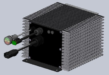
The battery charger is a
self-regulating charger with a minimum of moving parts, designed for long,
trouble free service. The charger
utilizes convection cooling which maximizes the reliability and minimizes any
maintenance costs.
Charge time will vary depending on the depth of discharge. Allow 8 hours for normal charging.
Charging Procedure
1. Connect the AC supply cord to the correct single phase outlet,
located in the front bumper of the vehicle, with one of the proper voltages and
frequencies
as
follows:
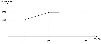
Electrical specifications of charger
Rated supply voltage : 85VAC to 138VAC and 195VAC to
265VAC
Automatic AC Voltage Selection
Mains frequency : 45/65Hz
Inrush current: limited by NTC, Input current
electronically limited (for low line) to 15Arms
Max. output power: 1500W +/- 3%
Max. output current : 21A +/- 2%
Rated battery voltage : 72V
Voltage tolerance at threshold U : 1%
 2. The charger will start after a
short delay as indicated by the light in the round display located through the
front grill of the hood.
2. The charger will start after a
short delay as indicated by the light in the round display located through the
front grill of the hood.
3. Through the grill of the hood
in the front of the vehicle towards the driver’s side there is a LED light that
shows the state that the charger is in. Around this light is a sticker that
looks like this diagram that explains what each of the three colors of the light mean:
 Red
(20% battery charged) Green
(100% charged)
Red
(20% battery charged) Green
(100% charged)
Yellow (80% battery charged) Off (No AC power is connected
4. Once the charge is completed the charger will turn off automatically. After the charger has turned off, disconnect the AC supply cord from the outlet.
5. Anti-Drive
When a power cord is plugged into the front outlet of the vehicle and power is present the vehicle will power up but it will not move. In any case were AC power is still present at the front AC charger outlet make sure to have the park brake set and the ignition key turned off before you exit the vehicle. After the AC cord is disconnected from the front charger outlet, restart the vehicle and disengage the park brake and the vehicle will move.
6. Trickle
charge
When the charger AC cord stays connected to the vehicle, a new charge cycle is triggered 24 hours after the end of the last charge cycle in order to compensate the auto-discharge.
7. Partial
recharge
The charger is designed to adapt automatically to all battery discharge states and allows all types of partial charge cycles or "opportunity charging". Meaning the vehicle can be charged at anytime no mater what the state of charge is.
Chargers Automatic Operations
- Over lasting charge
period
The charge cycle is interrupted when duration of phases I1+P+U1 exceed 16 hours. This problem may occur if a battery element failed (short-circuit) or when ambient temperature is too high. Check the battery state.Return to normal state by disconnection of the mains for a few seconds, followed by its reconnection.
- Mains power
interruption
In case of temporary power cuts, all parameters of charge in progress are stored in memory for a period of 13 minutes. As soon as power is back, the charge cycle continues from the point (I, P, U1, U2, Stop) attained just before power cut. The number of ampere-hours already charged has been stored in the memory of the microcontroller. If the power cut lasts more than 13 minutes, the charger assumes that the vehicle has been used and a complete charge cycle is started. It means, for restarting or resetting a new charging cycle, the mains must be disconnected at least 13 minutes.
- Protections against
mains out of range:
I.
If the mains voltage drops under the minimum allowed
value (see specs), the charger automatically stops. It will automatically
re-start as soon as the mains voltage comes back into the
given tolerances. For low input voltage range, the charger will
automatically reduce its output power to keep input
current below 15A.
II.
If the mains voltage goes over the maximum allowed
value (see specs), the charger automatically stops.
III.
Non significant over voltage: the charger will
automatically re-start after about 20 seconds if mains voltage comes back into the
given tolerances.
IV. Significant over voltage: after about 1 minute, the charger will automatically try to re-start. If mains voltage does not come back into the given tolerances, the charger will stay in default state and will be able to re-start only after a mains disconnection (mains voltage in the given range).
- Thermal protection:
The charger will automatically reduce its output power to maintain safe internal temperature and a maximum outside temperature of 65°C.
- Charge Profile:
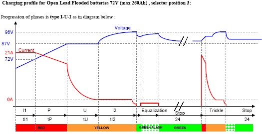
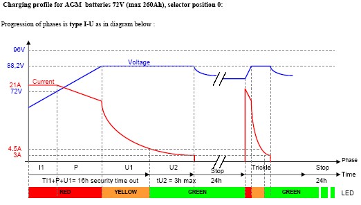
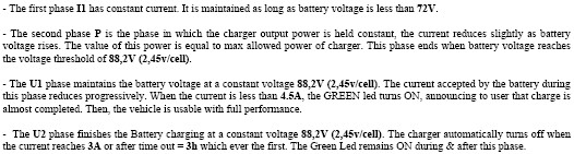
·
LED
light is red during phases I1 and P (Bulk charge).
·
LED
light is yellow during phases U and I2.
·
LED
light is green flashing during cyclic equalization
·
LED
light is green when charger has completed charging batteries.
· LED light is off when main supply is switched off
Charging with different battery types
At the rear of the battery charger there are two rubber
plugs. If you remove the rubber plug on the left side of the charger you will
find a DIP switch. The switch has four settings to it which are all numbered
0-3. Each number correlates to a battery type.

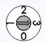 Setting
Position 0:
AGM
battery
Position
1: GEL
battery
Position 2:
Free
(Open lead flooded battery by default)
Position 3: OPEN lead flooded battery
Charging Battery Pack with Low
In most cases the battery charger will not turn on if the battery pack voltage gets lower than 20 volts. In this case each battery will need to be charged individually with a different battery charger.
Vehicles equipped with an AC cab heater
Note that vehicles equipped with an
AC cab heater this charger is wired on the same inlet plug. This adds
complications when diagnosing an issue. See Electrical Systems section under
order of operations than 120 volt AC Heater (Vehicle built date after 1/11/10).