The Topic Is For
Battery Type/'s
-Lithum 100AH 3.3KW Charger-Lithum 200AH 3.3KW Charger
-Lithum 100AH 6.6KW Charger
-Lithum 200AH 3.3KW Charger
Manufacture Dates
Between 08/07/2014 Thru 12/31/2024
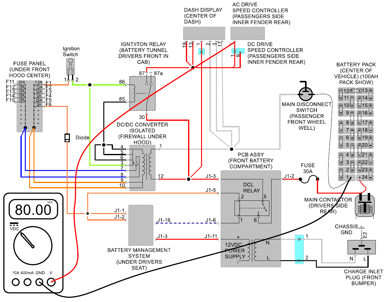
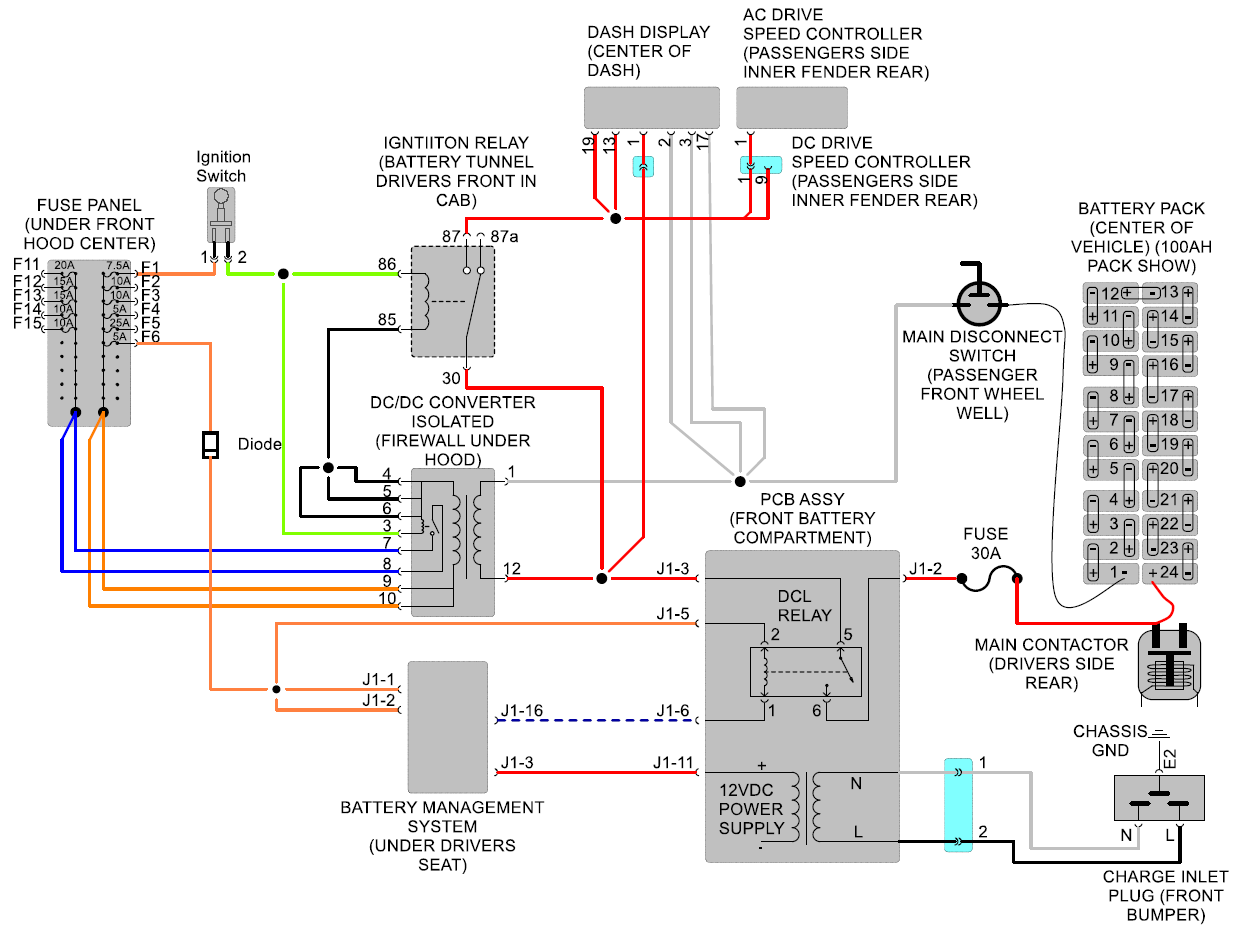
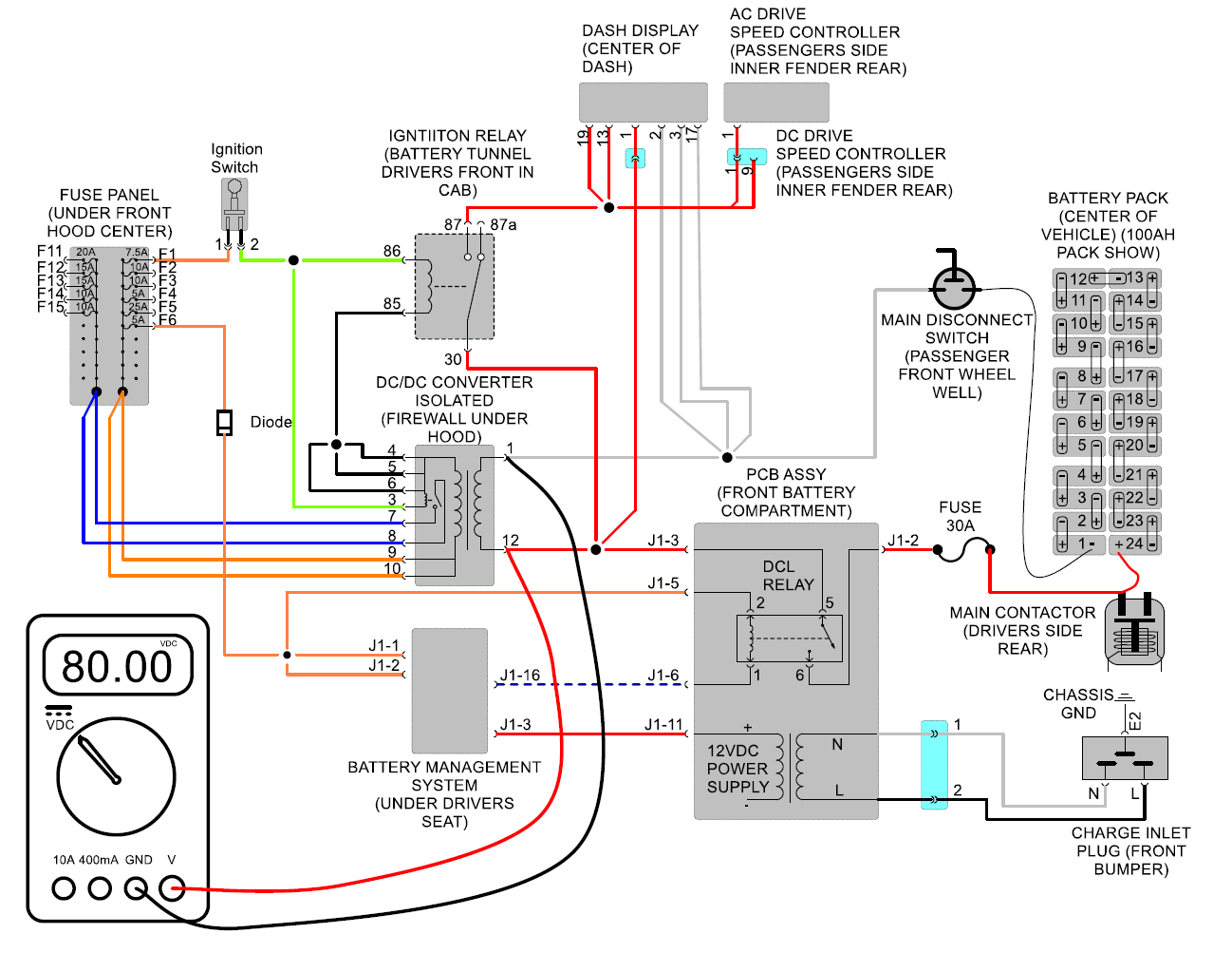
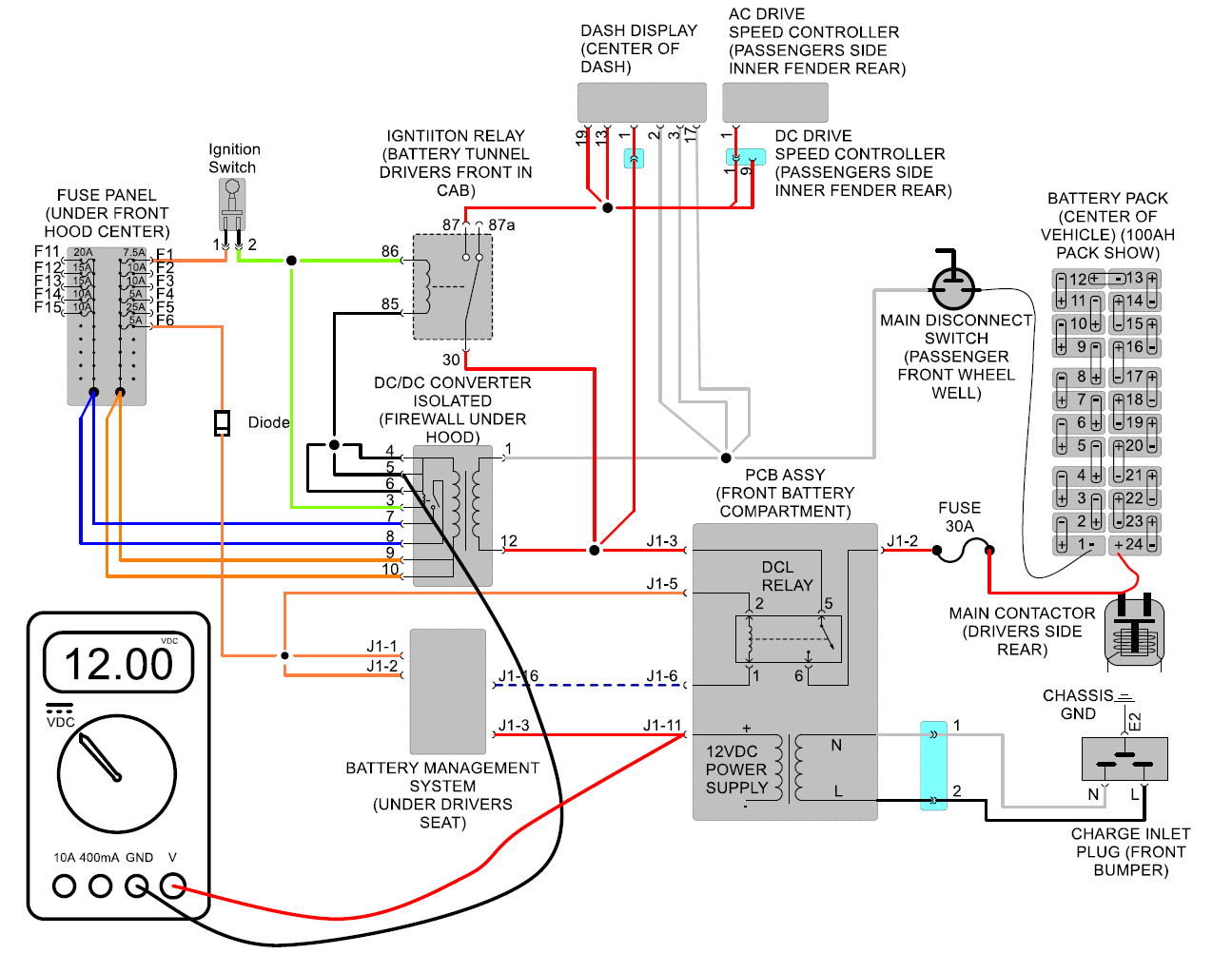
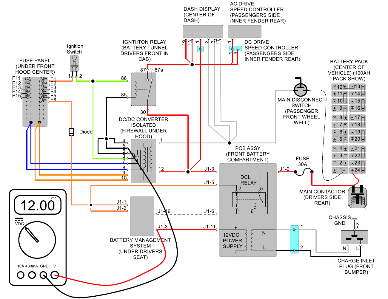
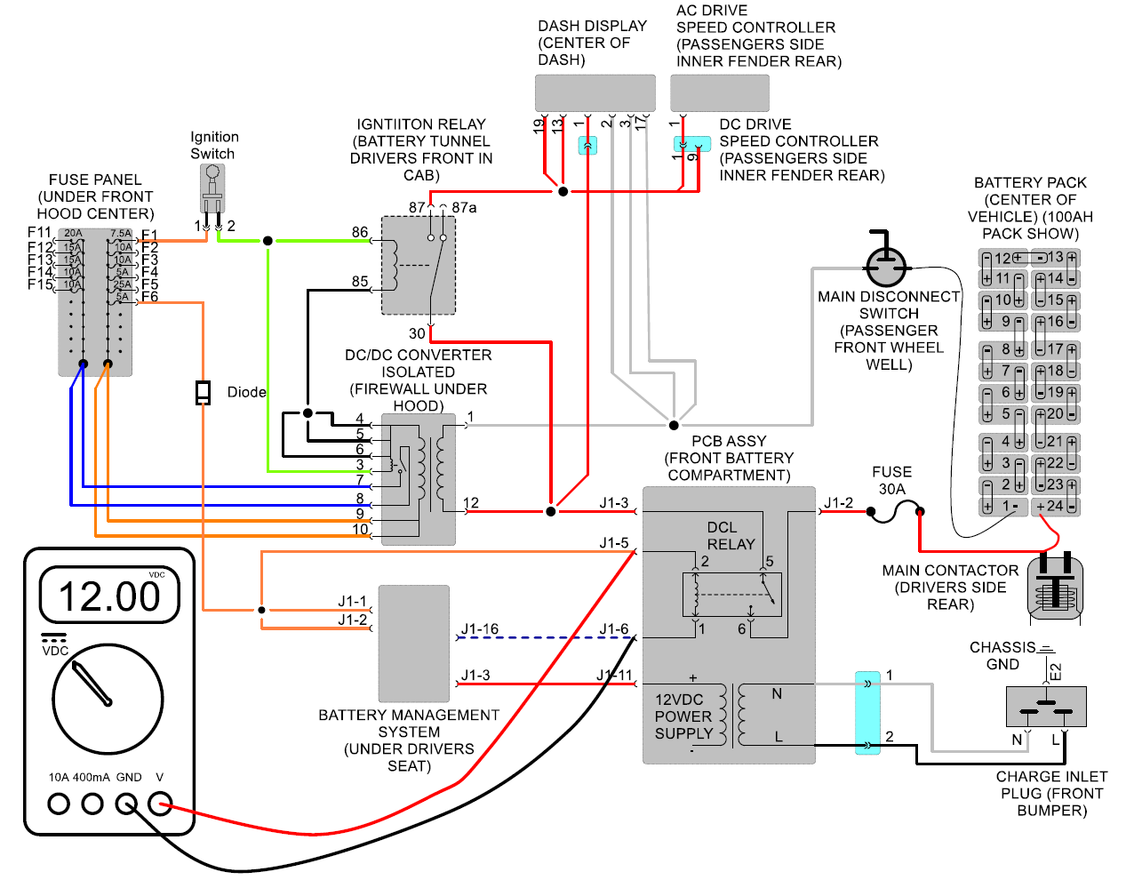
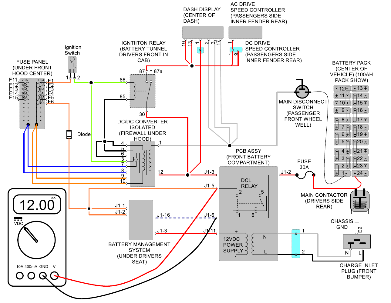
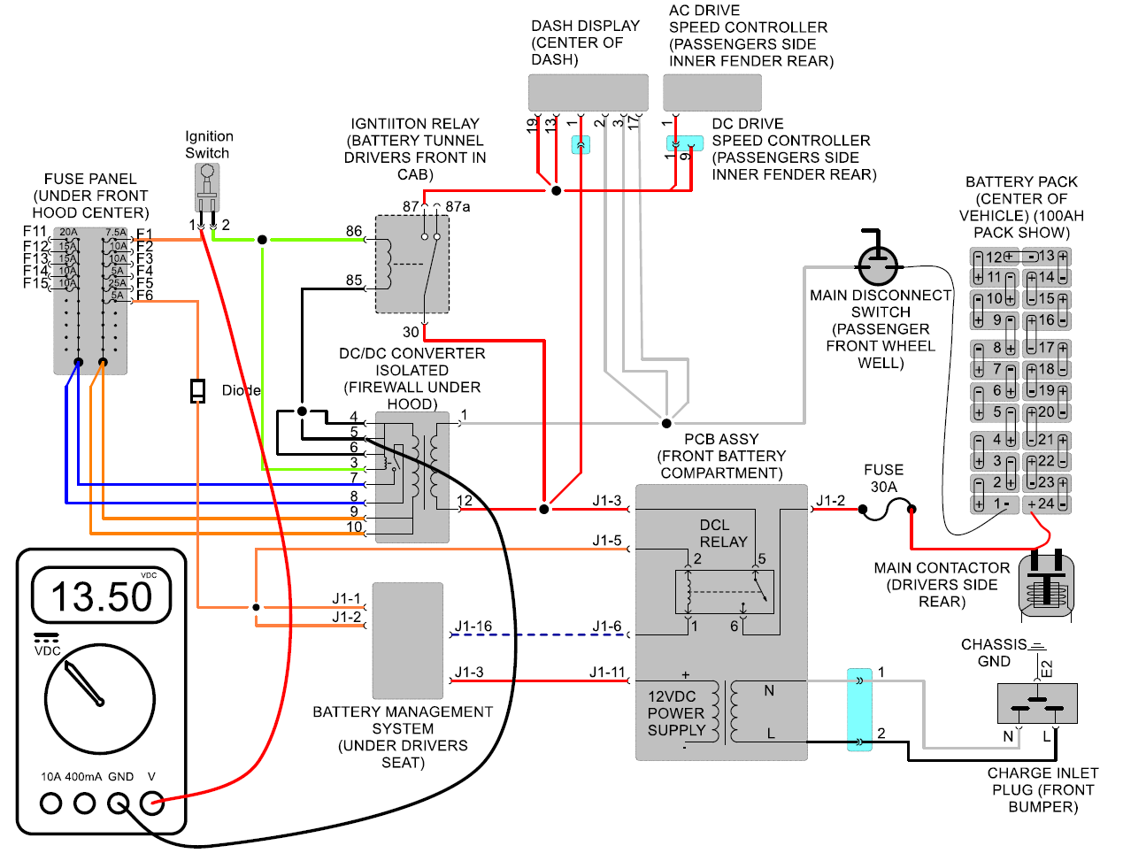
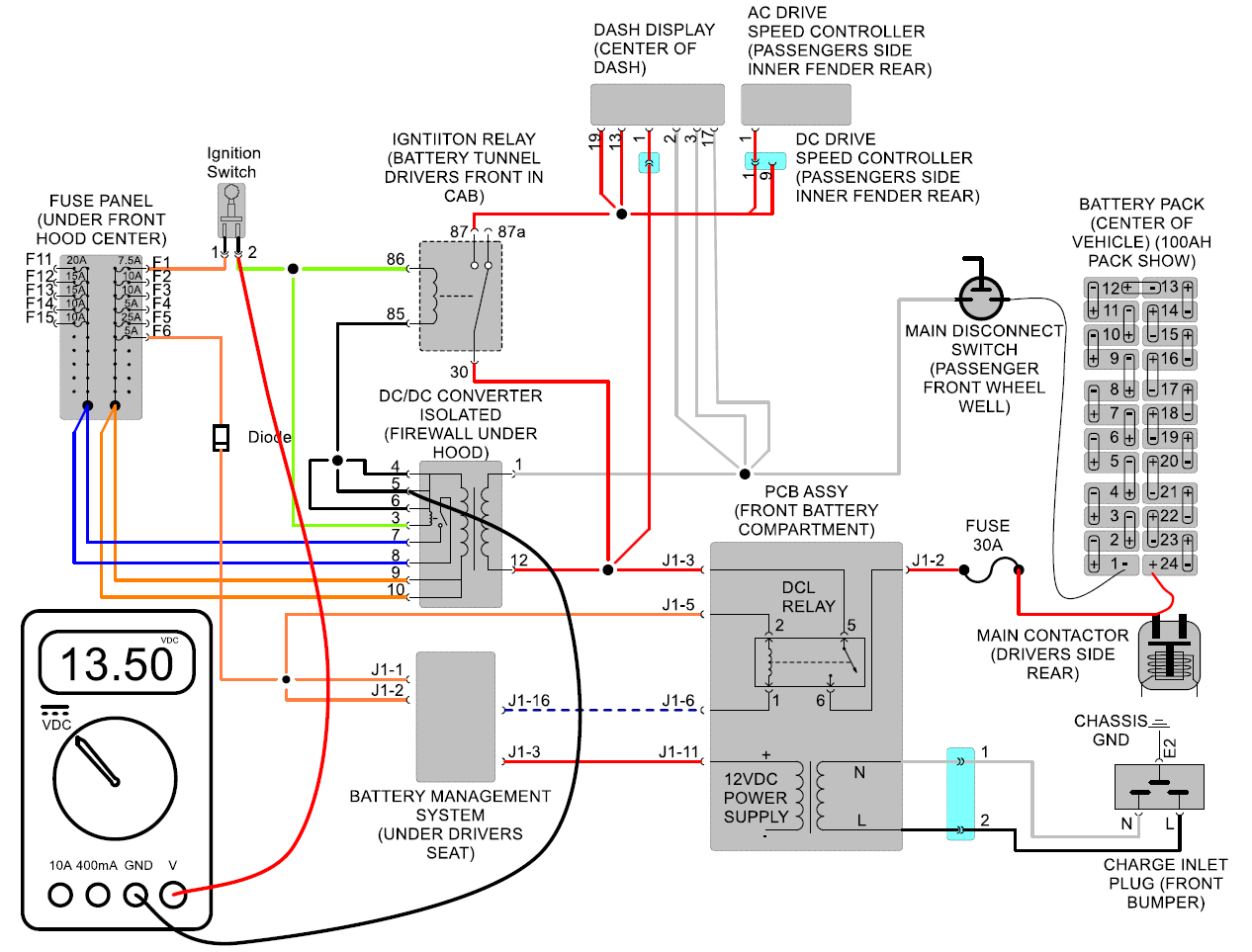
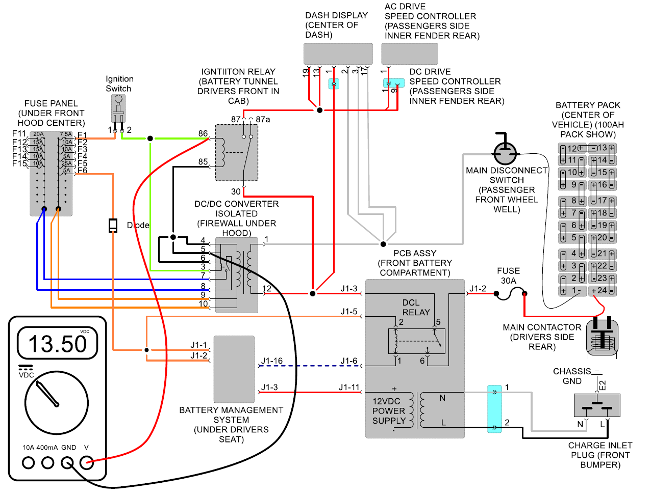
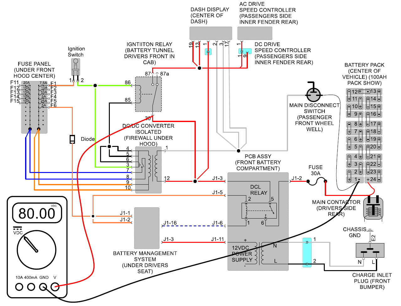
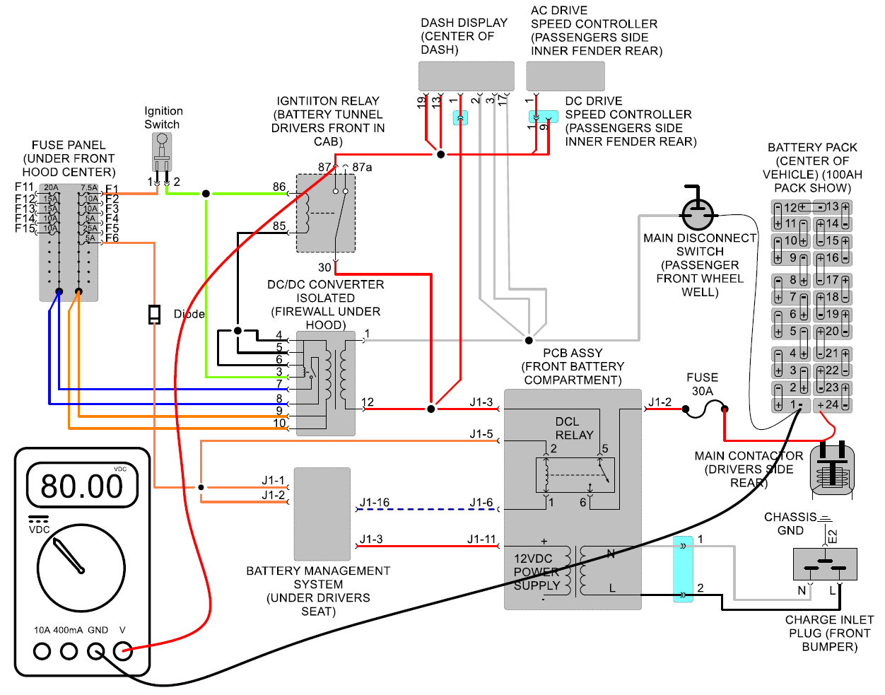
Ignition Circuit Wiring diagram
Test #1
Measure voltage between pin#1 pin#12 of DC/DC converter 12 pin connector. Connector
can be unplugged for this test
but have the front bumper plugged in like
as if you were charging vehicle. Should
measure battery pack voltage which is typically about 80 volts DC.
If so, see test #2.
If not see test #1-2
Test #1-2
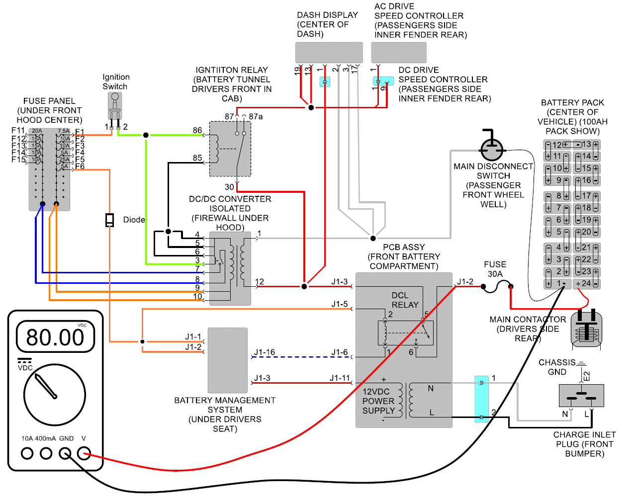
Measure voltage between pin #4, 5 or 6 of DC/DC converter 12 pin connector (Connector must
be plugged in for this test) or any
small black wire at the 15-pin connector
going to center console and pin #11 of PCB assy. Have vehicle plugged in at the front
bumper as if it were
charging. Also, connector must remain
plugged into the PCB assy. for this test. You should measure about 12 volts
DC.
If so, see test #1-3
If not see test #1-2-2
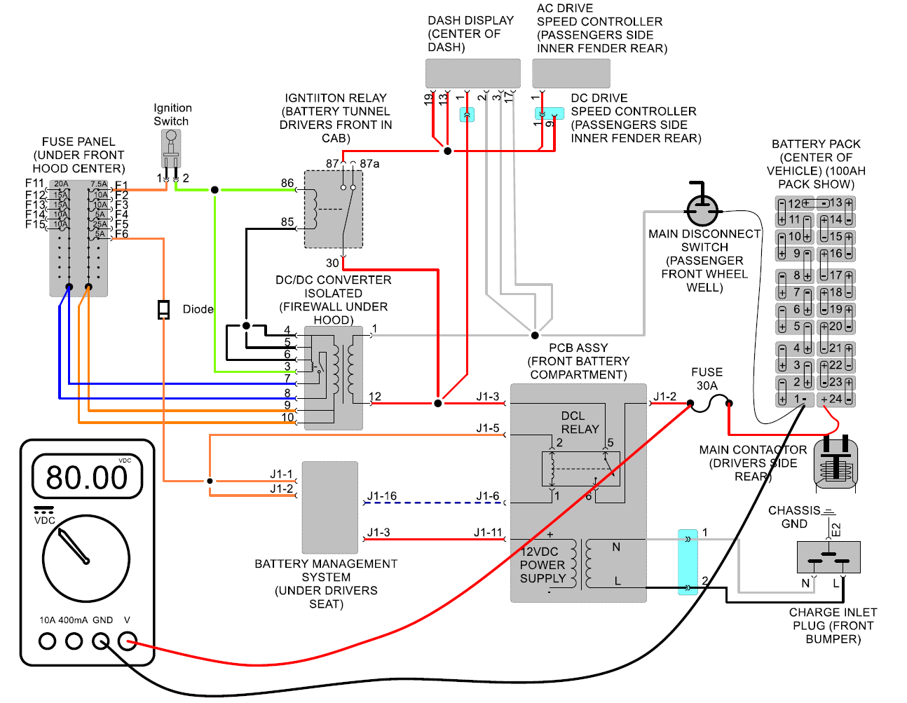
Test #1-2-2
At the battery management system located under the drivers seat. Locate the main I/O
connector which is white and has 26 pin
locations. Measure voltage between pin #3
and pin #4, 5 or 6 of DC/DC converter 12 pin
connector (Connector must be plugged in for this test) or any small black wire at the 15
pin connector going to center console. Have
vehicle plugged in at the front bumper as
if it were charging. Also connector must remain plugged into the BMS for this
test. You should measure about 12 volts DC.
If so, see test #1-3
If not more than likely the battery management system has an internal fault the DCL relay will not
close and this fault must be corrected. Or also see
test #1-2-3
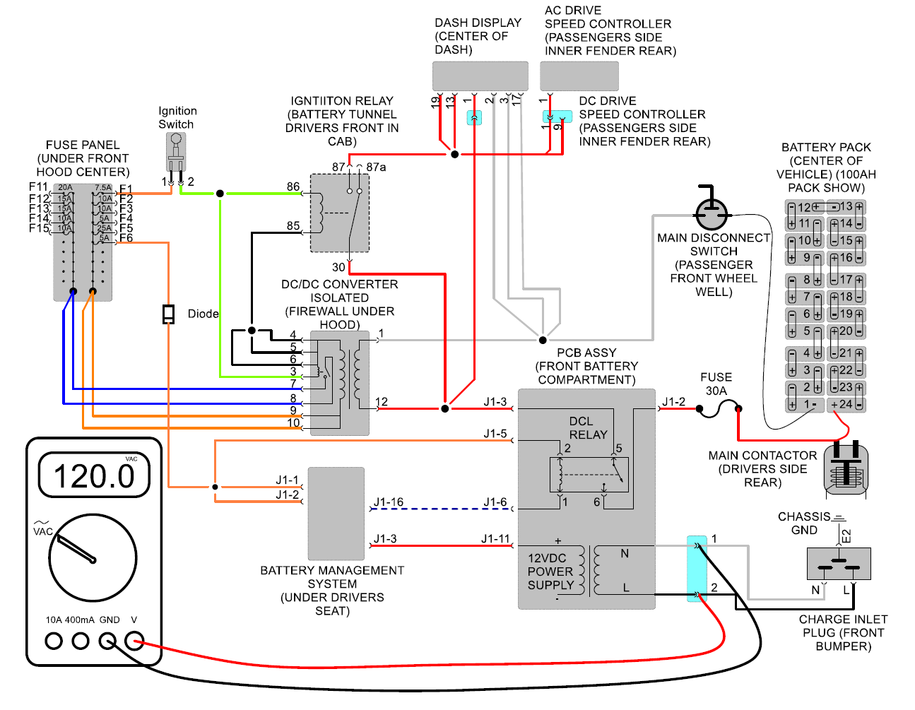
Test #1-2-3
Measure voltage between pin #1 and #2 of gray 4 pin connector if the pcb assy. Have
vehicle plugged in at the front bumper
like its charging. You should measure
the same AC voltage plugged into the front bumper 120VAC or
220VAC. If so the PCB assy is bad and needs to be
replaced.
If not then either you have no power at the front inlet plug, a wiring issue between the inlet and this gray connector or wiring/plug issue at the charge port in the front bumper.
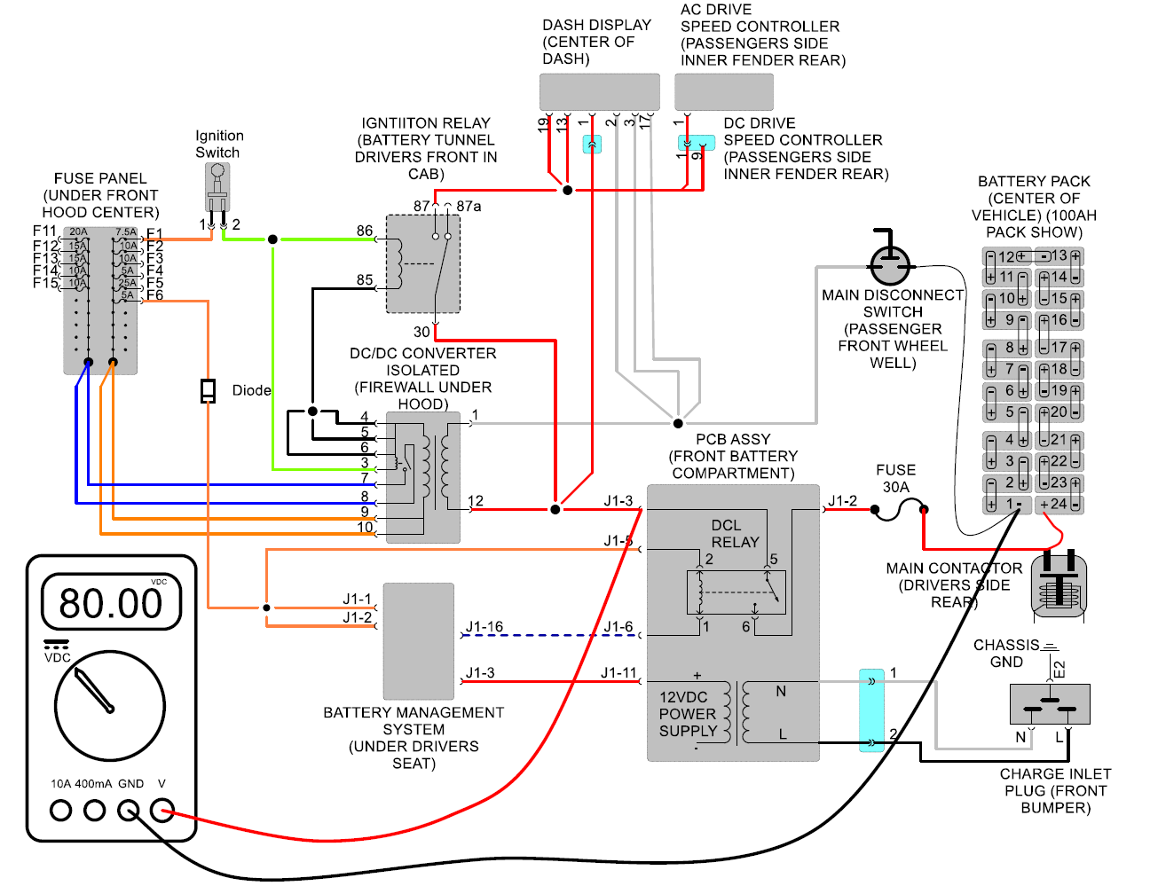
Test #1-3
At the battery management system located under the drivers seat. Locate the
main I/O connector which is white and
has 26 pin locations. Measure
voltage between pin #3 and pin #4, 5 or 6 of DC/DC converter 12 pin
connector (Connector must be plugged in for this test) or any small black wire
at the 15 pin connector going to center
console. Have vehicle plugged in at the front bumper as if it were
charging. You should measure
about 12 volts DC.
If so, see test #1-4
If not, you have a wiring issue between the battery management system and pcb
assy.
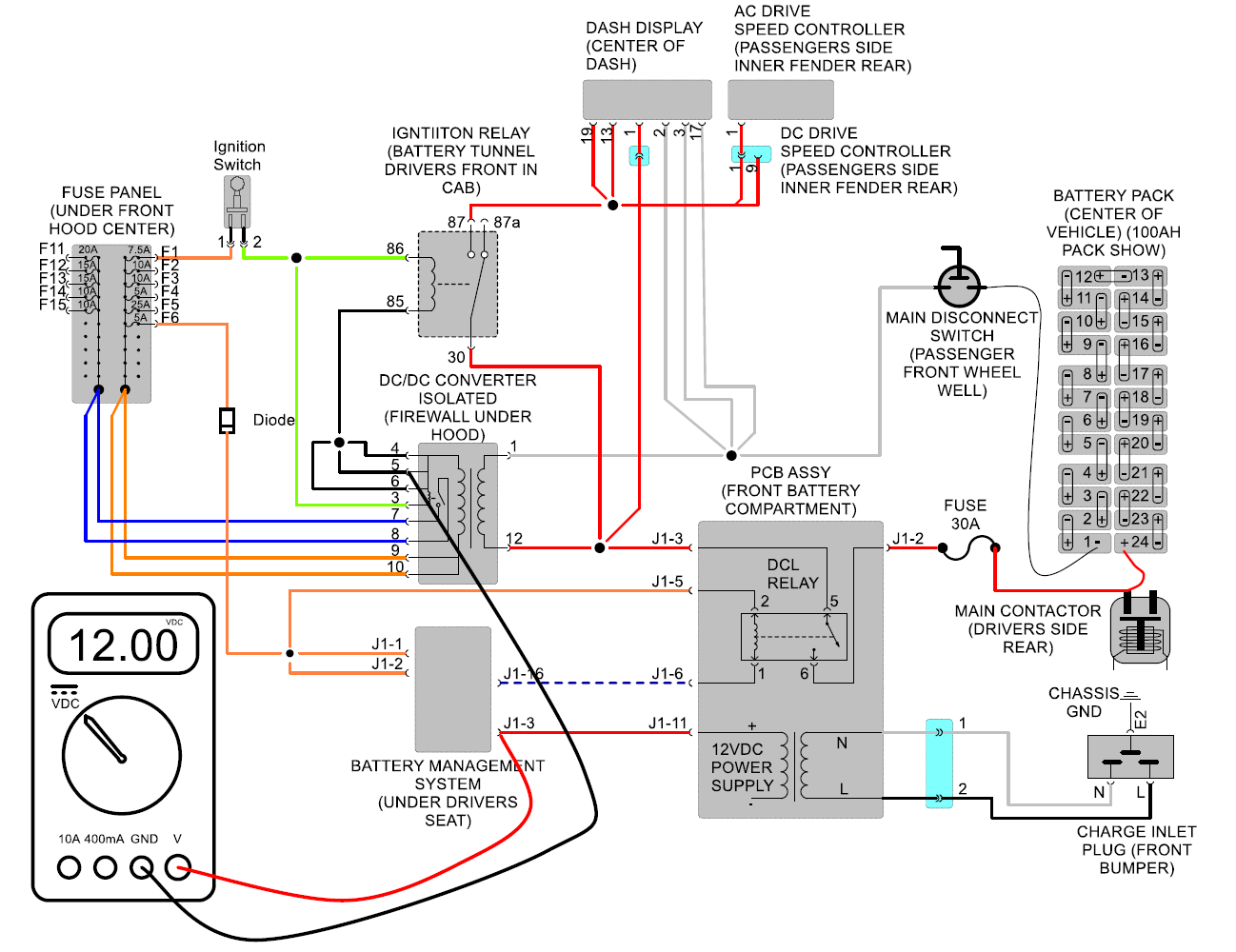
Test #1-4
At the battery management system located under the driver's seat. Locate the
main I/O connector which is white
and has 26 pin locations. Measure voltage between pin #3 and pin #16.
Have vehicle plugged in at
the front bumper as if it were charging. Also, connector must remain
plugged into the BMS for
this test. You should
measure about 12 volts DC.
If so, see test #1-5
If not more than likely the battery management system has an internal fault the DCL relay will not close, and this fault must be corrected. In order to read fault code, you will require a computer and diagnostic cable part# U5665A-N.
If not more than likely the battery management system has an internal fault the DCL relay will not close, and this fault must be corrected. In order to read fault code, you will require a computer and diagnostic cable part# U5665A-N.
Test #1-5
At the lithium PCB assembly located at the front of the battery pack. Locate the
main I/O connector which is
black. Measure voltage between pin
#5 and pin #6. Have vehicle plugged in at the front bumper as if it were charging.
You
should measure about 12 volts
DC.
If not, you may have a connection issue between battery management system and pcb assy. but also see test #1-5-2.
If so, see test #1-6.
If not, you may have a connection issue between battery management system and pcb assy. but also see test #1-5-2.
If so, see test #1-6.
Test #1-5-2
Measure voltage between B- of main battery pack and pin #2 of black
connector at pcb assy. You should measure pack voltage
typically 80VDC.
If so, see test #1-5-3
If not see test # 1-5-2-2
Test #1-5-2-2
Measure voltage between B- of main battery pack and both sides of main 30-amp
fuse located in the driver's side rear of
vehicle. You should measure
pack voltage typically 80VDC on both sides.
If so, then you have a wiring issue between the fuse and pcb assy.
If you have power on one side, then fuse is blown replace and retest.
If no power on either side, then you have a connection issue between 30A fuse and
battery pack.
Test #1-5-3
Measure voltage between B- of main battery pack and pin #3 of black
connector at pcb assy. Connector must
remain plugged in for this test. You should measure pack voltage typically 80VDC.
If not, pcb assy is bad and needs to be replaced.
If so, you have a wiring issue between pcb assy and converter.
Test #1-6
At the lithium PCB assembly located at the front of the battery
pack. Locate the main I/O connector which is
black. Measure voltage
between pin #5 and pin #6. Have vehicle plugged in at the front bumper
as if it were
charging. You should measure about 12 volts DC.
If not, you may have a connection issue between battery management system.
and pcb assy. but also see test #1-5-2.
If so, see test #1-6.
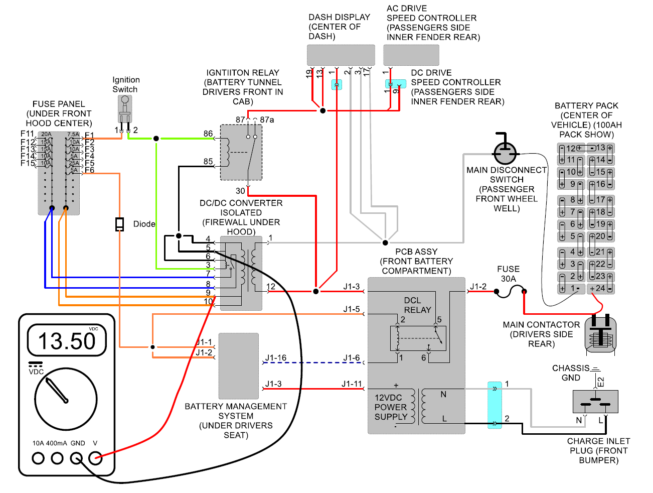
Test #2
Measure voltage between pin#4, 5 or 6 pin#9 or 10 of DC/DC
converter 12 pin connector. Connector must be
plugged in for this test. Should measure about 13.5 volts
DC.
If so, see test #3.
If not DC/DC converter is bad and needs to be replaced.
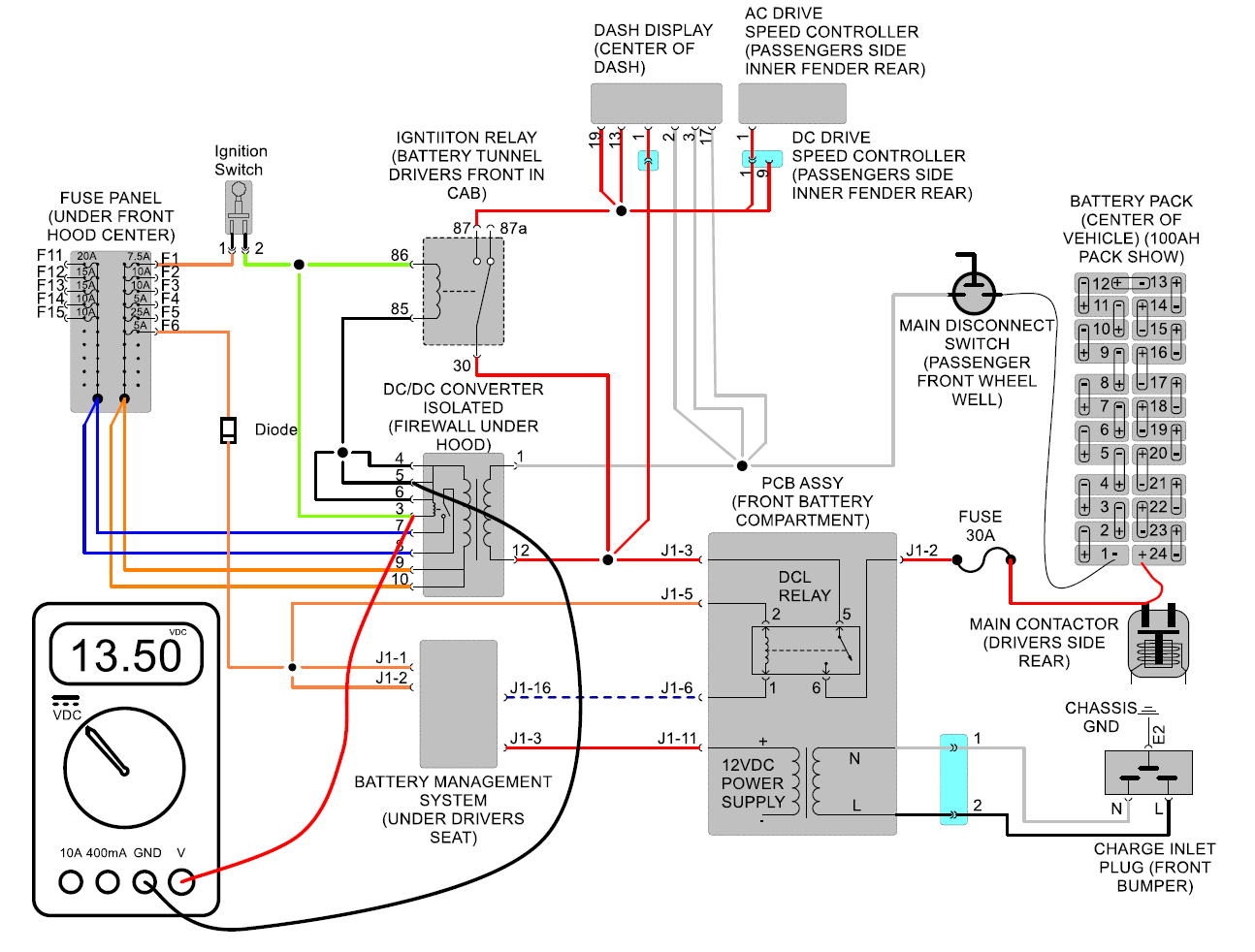
Test #3
Measure voltage between pins #4, 5 or 6 pin #3 of DC/DC
converter 12 pin
connector. Connector must be plugged in for this test. Ignition
key needs to be
in the on position. Should measure about 13.5 volts
DC.
If so, see test #4
If not see test #5
Test #4
Measure voltage between pin #4, 5 or 6 pin #7 or 8 of DC/DC
converter 12 pin connector. Connector must be
plugged in for this test. Ignition key needs to be in the on
position. Should
measure about 13.5 volts DC.
If so, DC/DC converter is bad and needs to
be replaced.
If not see test #5

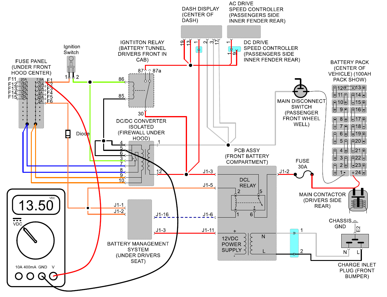
Test #5
Measure voltage between pin #4, 5 or 6 of DC/DC converter 12
pin connector (Connector
must be plugged in for this test) and top of F1 fuse. Both
sides of fuse should measure
13.5 volts DC.
If only one side fuse is blown, try new good fuse and retest.
If neither side measure voltage, then you have a
wiring/connection issue in the fuse panel or between fuse
panel and DC/DC
converter.
Test #6
Measure voltage between pin #4, 5 or 6 of DC/DC converter 12
pin connector (Connector must
be plugged in for this test) or any small black wire
at the 15-pin
connector going to center console and pin #1 of
ignition switch. Should measure 13.5 volts
DC.
If so, see test #7.
If not, you have a wiring issue between the ignition switch and F1 fuse
panel.
Test #7
Measure voltage between pin #4, 5 or 6 of DC/DC converter 12
pin connector
(Connector must be plugged in for this test) or any small
black wire at the 15-pin
connector going to center console and pin #2
of ignition switch with
ignition switch in the on position. Should measure
13.5
volts DC.
If so, see test #8.
If not, you have a bad ignition switch.
Test #8
Measure voltage between pin #4, 5 or 6 of DC/DC converter
12 pin connector
(Connector must be plugged in for this test) or any small
black wire at the
15-pin connector going to center console and pin #86
of ignition switch
relay with ignition switch in the on
position. Should measure
13.5 volts DC.
If so, see test #9.
If not, you have a wiring issue between ignition switch
and ignition switch relay.
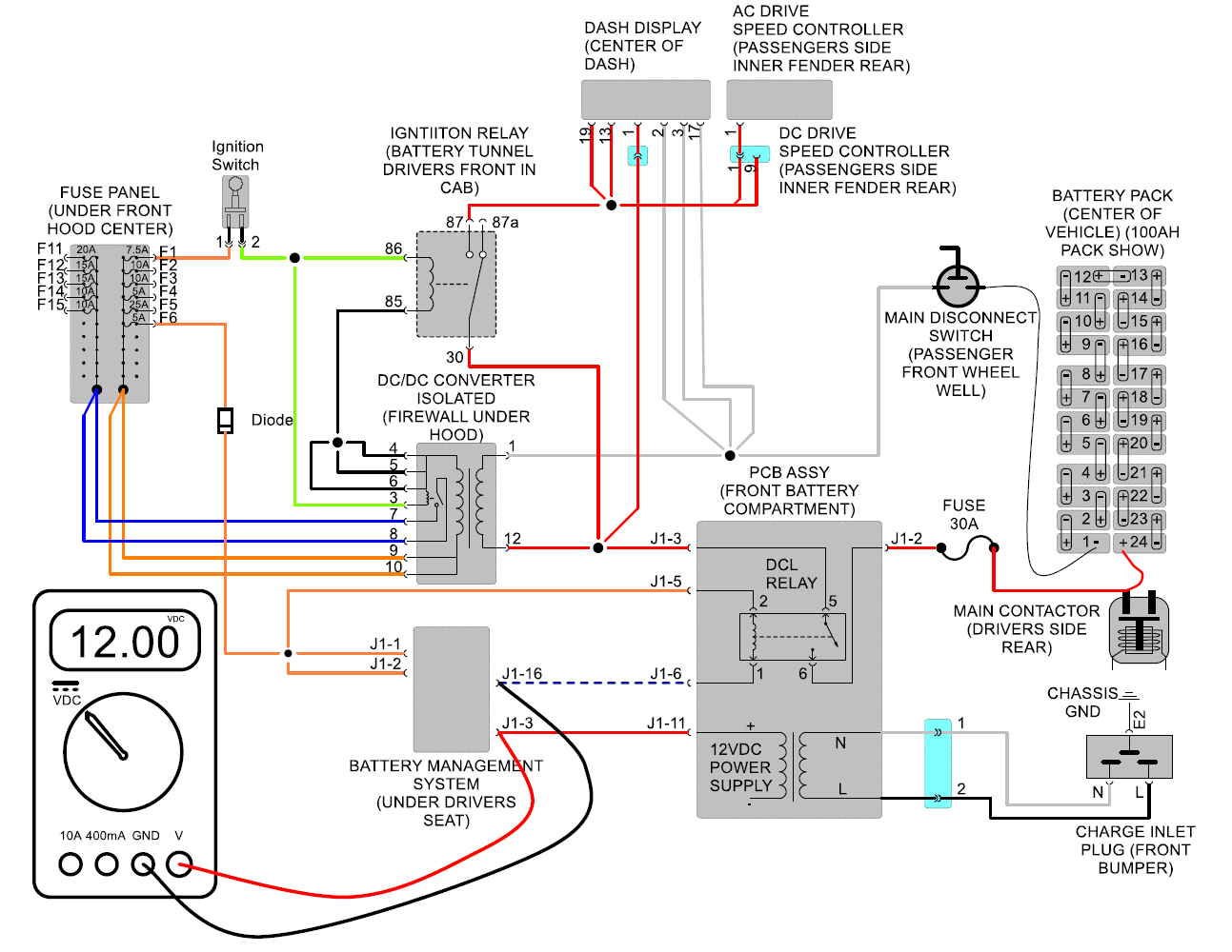
Test #9
Measure voltage between B- of main battery pack and
pin #30 of ignition
switch relay Should
measure pack voltage typically about 80 volts.
If so, see test #10.
If not since test #1 tested good, then you would have
a wiring issue between the ignition relay and the wiring harness
splice.
Test #10
Measure voltage between B- of main battery pack
and pin #87 of ignition
switch relay with ignition switch in the on
position Should
measure pack voltage typically about 80 volts.
If so,
see test #11.
If not, ignition relay is bad and needs to be
replaced.
Test #11
Measure voltage between B- of main battery
pack or speed controller and pin #1 of speed controller
with ignition switch in the on
position Should
measure pack voltage typically about 80
volts.
If so and controller is not powered (no LED
lights) controller is bad and needs to be
replaced.
If not, you have a wiring issue between the
ignition relay and speed controller.