Battery Type/'s
-Lithum 100AH 3.3KW Charger-Lithum 200AH 3.3KW Charger
-Lithum 100AH 6.6KW Charger
-Lithum 200AH 3.3KW Charger
Manufacture Dates
Between 11/30/2001 Thru 12/31/1969
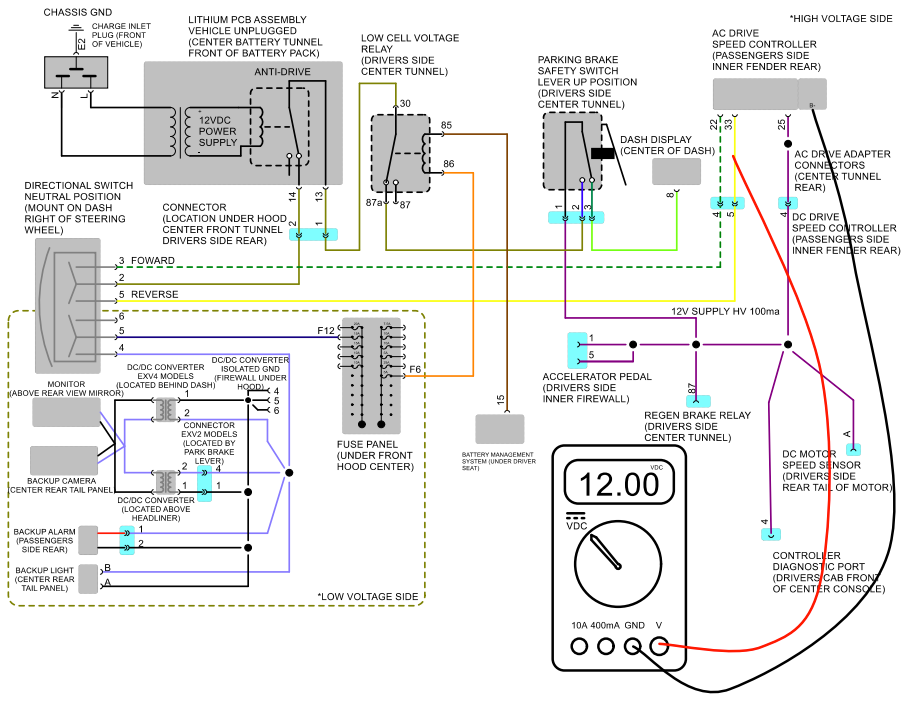
WIRING DIAGRAM DIRECTIONAL CIRCUIT
TEST #1
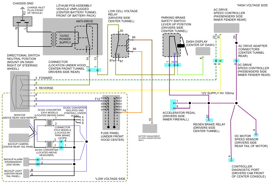
Measure between pin# 1 of parking brake switch connector and main negative of battery pack (drivers side rear) Should measure 12VDC with ignition key on. If yes, see test #2. If no, see test #1-2
TEST# 1-2
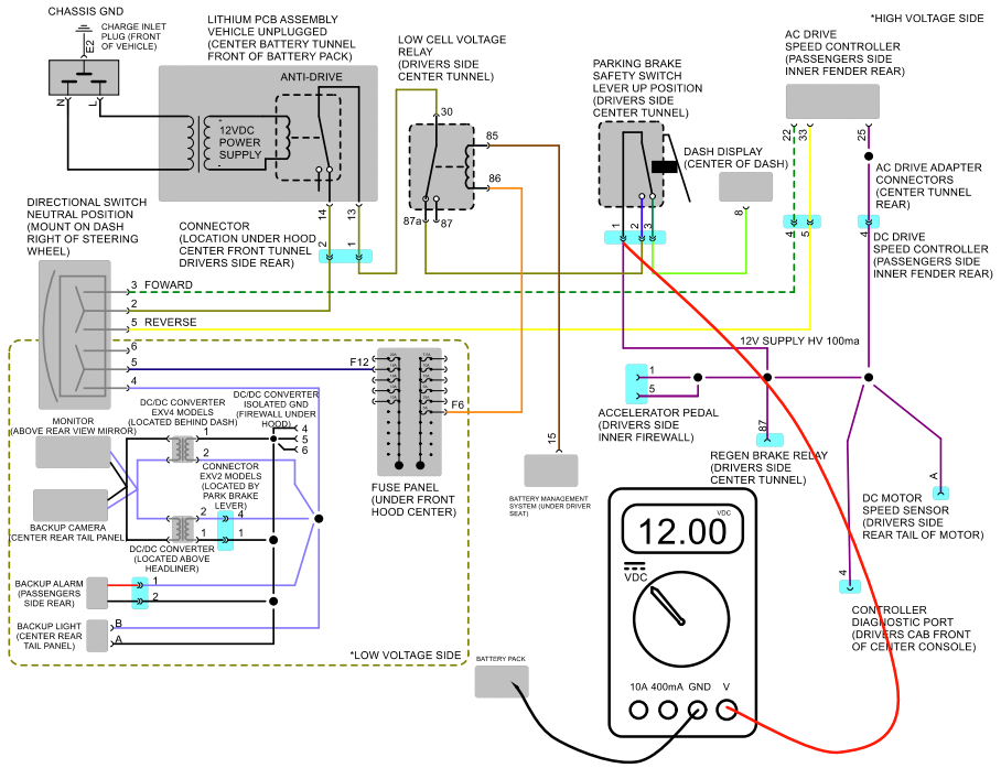
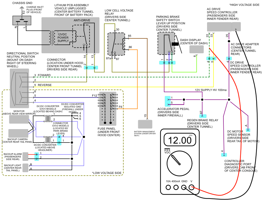
This test depends on if vehicle is AC or DC drive. For AC drive measure between pin #25 of speed controller. For DC drive measure between pin #4 of speed controller 4 pin connector and B- battery cable connection on speed controller. Should measure 12VDC with ignition key on. If so, you have a connection/wiring issue between this test point and parking brake switch. If not, controller is defective and needs to be replaced.
Test#2
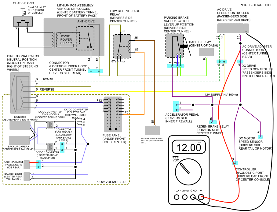
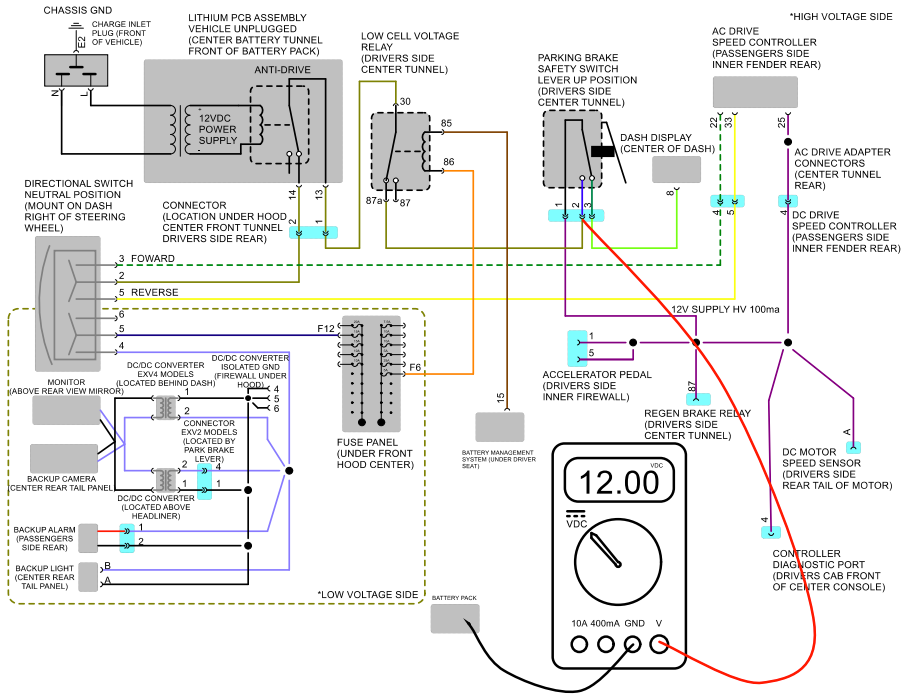
Measure between pin# 2 of parking brake switch connector and main negative of battery pack (drivers side rear). Should measure 12VDC with ignition key on and parking brake released. If so, see test #3. If not parking brake switch is bad and needs to be replaced.
Test#3
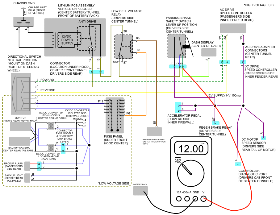
Measure between pin# 3 of parking brake switch connector and main negative of battery pack (drivers side rear). Should measure 12VDC with ignition key on and parking brake lever set. Also parking brake emblem should be shown in the dash display. If so, see test #4. If not parking brake switch is bad and needs to be replaced.
Test #4
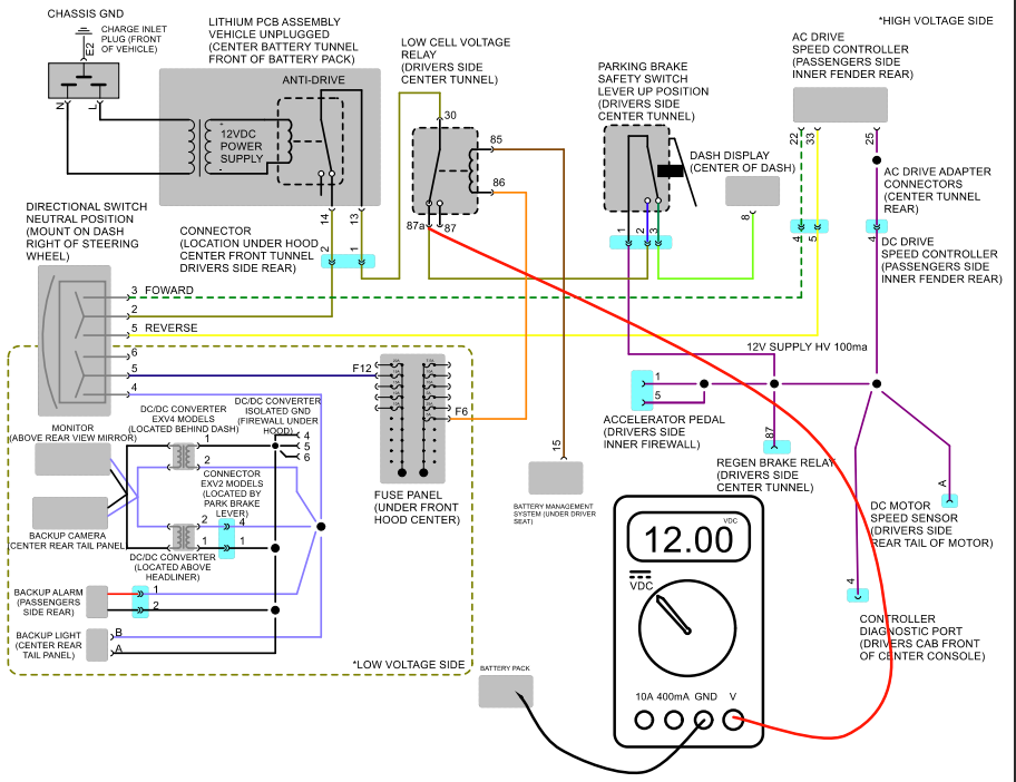
Measure between pin# 87a of low cell voltage relay and main negative of battery pack (drivers side rear). Should measure 12VDC with ignition key on and parking brake released. If so, see test #5. If not, you have a wiring/connection find and fix.
TEST #5
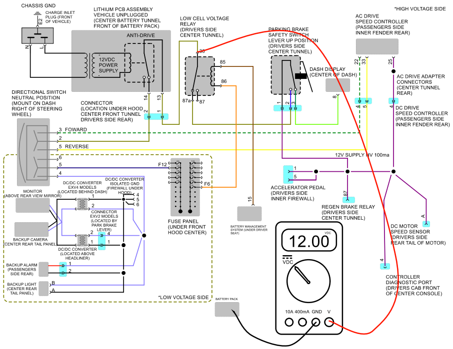
Measure between pin# 30 of low cell voltage relay and main negative of battery pack (drivers side rear). Should measure 12VDC with ignition key on and parking brake released. If so, see test #6. If not, see test #5-1.
TEST #5-1
Measure between pin# 85 & pin# 86 of low cell voltage relay. Should measure 0 VDC. If so, see test #7. If not you more than likely will be measuring about 12VDC which means the lithium battery management system is measuring low voltage on one or more cells. See lithium battery testing.
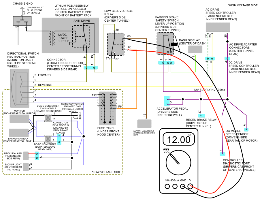
Test #6
Measure between pin# 13 of lithium PCB assembly or #1 of connector shown and main negative of battery pack (drivers side rear). Should measure 12VDC with ignition key on and park brake released. If so, see test #7. If not, you have a wiring/connection issue between low cell voltage relay and lithium PCB assembly.
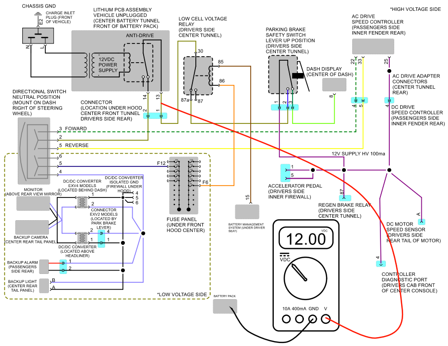
TEST #7
Measure between pin# 14 of lithium PCB assembly or #2 of connector shown and main negative of battery pack (drivers side rear). Should measure 12VDC with ignition key on and park brake released. If so, see test #8. If not, you have a bad lithium PCB assembly.
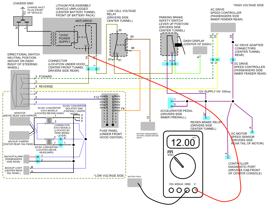
TEST #8
Measure between pin# 2 of directional switch and main negative of battery pack (drivers side rear). Should measure 12VDC with ignition key on and parking brake released. If so, see test #9. If not, you have a wiring/connection issue between lithium PCB assembly and directional switch.
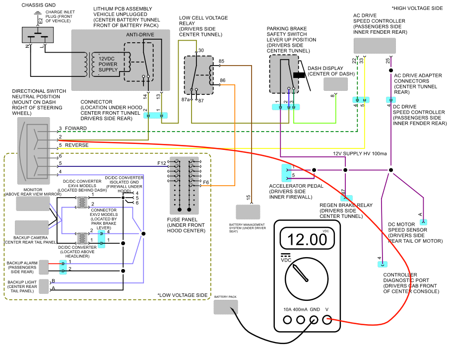
TEST #9
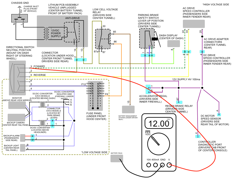
Measure between pin# 3 of directional switch and main negative of battery pack (drivers side rear). Should measure 12VDC with ignition key on, parking brake released and directional switch in the forward position. If so, see test #10. If you need to test the reverse circuit, see test 11. If not, you have a bad directional switch.
Test #10
This test depends on if vehicle is AC or DC drive. For AC drive measure between pin #22 of speed controller and For DC drive measure between pin #4 of speed controller 24 pin connector and B- battery cable connection on speed controller Should measure 12VDC with ignition key on, park brake released and directional switch in forward. If so, and vehicle has 0 movement in forward the issue is not related to the direction circuit. If not, you have a wiring/connection issue between directional switch and controller.
Test #11
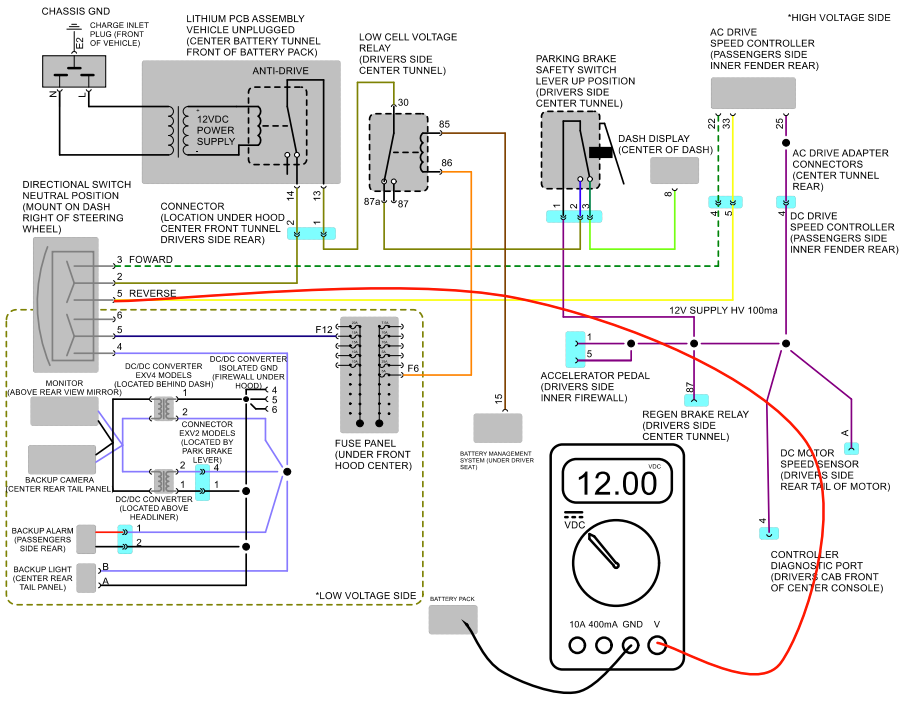
Measure between pin# 5 of directional switch and main negative of battery pack (drivers side rear). Should measure 12VDC with ignition key on, parking brake released and directional switch in the reverse position. If so, see test #12. If not, you have a bad directional switch.
Test #12
This test depends on if vehicle is AC or DC drive. For AC drive measure between pin #33 of speed controller. For DC drive measure between pin #5 of speed controller 24 pin connector and B- battery cable connection on speed controller. Should measure 12VDC with ignition key on, park brake released and directional switch in reverse. If so, and vehicle has 0 movement in forward the issue is not related to the direction circuit. If not, you have a wiring/connection issue between directional switch and controller.
