Year - Model
2005 - EXV22005 - EXV4
2006 - EXV2
2006 - EXV4
2007 - EXV2
2007 - EXV4
2008 - EXV2
2008 - EXV4
2009 - EXV2
2009 - EXV4
Battery Type/'s
-Flooded Lead Acid, Shut off
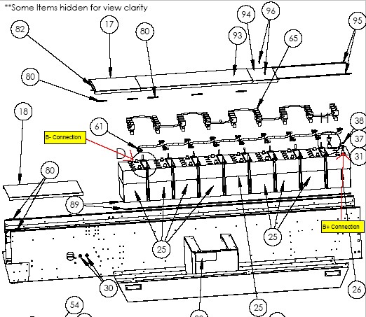
the main battery disconnect located in the front right wheel well. “WARNING” In
some cases the vehicle can be setup, so this disconnect does not shut off the
battery pack power at the charger. If you do not have the correct equipment to
test if power is present at the charger, then remove the battery cable from B-
of the first battery in the battery pack or/and B+ of the last battery in the
battery pack. Also make sure both front battery charger inlet plugs are
disconnected from the main power grid.
In order to access the front
battery in the pack the center console in the cab needs to be removed. Under
the center console are the tunnel covers which pull up. Below the cover you
will find the front battery. Note: Do not be mistaken, if the vehicle is AC
drive it will be equipped with a small 12-volt battery labeled U1L which would
be mounted in front of the battery pack inside the battery tunnel under this
cover. This battery only powers the 12-volt supply, and it has only 10-gauge
wires going to it. All connections should stay connected to this battery. The
cables that need to be removed from the front battery are 1/0 in size.
In order to access the rear battery
in the pack it depends on the model of the vehicle. If it is an EXV4 the rear
battery is accessed inside the cab under the tunnel cover as described above.
If it is an EXV2 it can be accessed through the flat bed access panel. If your
vehicle is built prior to September 2007, it will not be equipped with a flatbed
access panel. In order to access the rear battery on a vehicle built prior to
September 2007 the flatbed will have to be removed which needs to be done to
change the charger as well. Also, when removing the positive cable also remove
the two 10-gauge wires going to this post as well.
See Illustration of battery tunnel on last page.
How to access the charger
on the EXV2 Model:
In order to access the battery charger, the flatbed needs to be removed. In order to remove the rear flatbed, the four rear carriage bolts need to be removed. Also, inside the cab of the vehicle at the underside of the roof of the vehicle you will see either two rubber straps or two aluminum brackets held on by screws. Either style you have they need to be removed. Also depending on the manufacturing date of the vehicle you may have mounting screws at the front corners of the flatbed. In order to tell if you have these mounting bolts enter inside the cab and behind the seats at the front corners of the flatbed you will find a 7/8” diameter hole drilled in the rear enclosure. At the bottom of each hole will be a screw with a #3 Phillips head bolt. Remove these two bolts if you have them. If you do not have these bolts there will not be a 7/8” diameter hole. After this hardware is removed the flatbed can be lifted off the vehicle to gain access to the battery charger. Note: Your vehicle may be equipped with some sort of other option mounted to the flatbed which may or may not need to be removed to lift the flatbed from the vehicle.
How to access the charger
on the EXV4 Model:
In order to access the battery charger, the rear pickup box needs to be removed. To remove the rear pickup box first the rear enclosure needs to be removed. To remove the rear enclosure, enter into the rear of the cab and you will find screws that hold the enclosure to the rear pillar. Remove these screws. After the screws are removed the enclosure should become loose and can be removed. Next is to unbolt the pickup box. The box is held down by four carriage bolts which can be found by lifting up the box floor mat. Remove these bolts. Also, the box is held down by eight other bolts which can only be accessed by removing the two rear seats. The seats are removed by removing the four mounting nuts which are accessed through the seat base cut out at the front of the seat base. After removing the seats, you will find four 1/4 -20 bolts on each side of the vehicle. Remove all eight bolts. Next in order for the box to be lifted off the vehicle the plastic sail panels located on each side of the vehicle are held to the pickup box by one screw on each side. Remove these screws. Also to get enough clearance to lift the flatbed high enough to remove it the bottom two black rivets that hold the plastic sail panel to the rear pillar must be drilled out with a 3/16” rivet. Next is to disconnect or remove the taillight connector from the taillight lens. After this the pickup box can be lifted off the vehicle to gain access to the battery charger.
- How to mount new charger:
The
existing battery charger can be removed by unbolting the four nuts that hold
the charger to the vehicle. Depending on the manufacturing date of your vehicle
the AC inlet to the charger may be two independent 14/3 cords that have plugs
on them which are plugged into the battery charger inlet plugs or it may be
wired with one 14/4 power cord that is hardwired inside the battery charger. If
you have the two independent 14/3 power cords unscrew the plug retainers and
unplug the cords form the charger. If you have the 14/4 single power cord just
cut the cable from the battery charger. Next is to disconnect the DC side of
the charger. The DC wiring for the charger will be a power cord with two 10-gauge wires. Depending on when your vehicle was built these two 10-gauge wires
may either go to a gray connector which would be just a few feet from the
battery charger or there will not be a connector. We started using this
connector in the beginning to easy assembly, but dirt can get into the connector
causing connection and melting issues. If you have the connector, we recommend
that you cut the two 10-gauge wires on the vehicle side of the connector so the
connector would end up being removed. If you do not have this connector, just
take and cut the 10-gauge wires so they have enough length to reach the new
charger wire. Best to cut it as long as possible and make a second cut to the
correct length when wiring the new charger.
To install the new battery charger it will mount in the same location as the charger you just removed. It is not critical on the mounting of the charger just make sure the charger is mounted flat against the charger tray. The new battery charger needs the aluminum charger tray for extra heat sink. To make sure you have enough wire length it may be best to have the DC side of the new battery charger pointing towards the passenger’s side of the vehicle. Drill new holes in the charger mount tray using the new charger mount holes as a template. Bolt charger to battery tray using the supplied ¼-20 hardware.
To wire the DC side of the battery charger you need to first determine which of the two 10-gauge wires is positive or negative. “WARNING” Do not designate red as positive. Not all vehicles were wired with red as positive. Also, vehicles without the gray connector described above will have white and black colored wires. The only way to know which wires are positive and negative is to trace where they go. The positive wire is the easiest to trace. It should be running to B+ of the rear battery. After you discover which wire is positive the other 10-gauge wire is negative. As for the DC wiring of the new battery charger red is positive and white is negative. Take and splice the wiring together positive to positive and negative to negative. You can use the supplied 10-gauge butt connecters and heat shrink or your own other preferred method.
Decision to be made before
wiring the AC side of the battery charger
A decision needs to be made whether you want to charge the vehicle with 120 volts or 220 volts. The new charger can be either/or but for safety reasons it should be wired only to one of the inlet plugs. With the new battery charger is makes no difference on which voltage you power it with. With either power source it will perform exactly the same. The power inlet that you wish not to use can be removed from the vehicle all the way up to the front bumper. Note: If your vehicle is equipped with an aluminum unpainted bracket at the front bumper where the inlet plugs mount to, a single hole bracket can be purchased to replace the dual hole bracket if preferred. If no bracket is present and the front bumper has holes drilled into it, the front bumper would need to be replaced if you preferred a single hole.
Wiring AC side to battery
charger that has two 14/3 power cords
For vehicles wired with two 14/3 power cords one of the cords should have been removed from the decision you made above. The remaining cord needs to be cut and spliced to the 14/3 AC inlet cord of the battery charger. Black to black, white to white and green to green. You can use the supplied 14–16 gauge butt connecters and heat shrink or your own other preferred method. The other side of the battery charger cord plugs into the charger and the metal clip flips down to hold the cord in place.
Wiring AC side to battery
charger that has one 14/4 power cord
For vehicles wired with a single 14/4 power cord you will have to remove the inlet plug from the front bumper you wish not to use. The black and white wiring going to the inlet plug needs to be removed as it is only jumping between the two plugs. The red wire should be capped off. At the charger the 14/4 cord needs to be cut and spliced to the 14/3 AC inlet cord of the battery charger. Black to black, white to white and green to green. The red wire of the 14/4 cord needs to be capped off. You can use the supplied 14-16 gauge butt connecters and heat shrink or your own other preferred method. The other side of the battery charger cord plugs into the charger and the metal clip flips down to hold the cord in place.
The battery charger status indicator light
can be installed in different locations depending on how much work the install
chooses to put into it.
The easiest method is to just tie
strap the light to a component in the rear pointing to the underside of the
vehicle so that at any given time the operator could look under the vehicle to
make sure the charger is on.
The second
approach would be to drill a hole in the rear tail panel. Cut the wires to the
light, insert the light into the hole and re-splice the wires back together.
The third approach would be to cut the wires to the light and extend them so the light can be installed into the front of the vehicle. If light was installed behind the front hood grill, then the operator could make sure right away that the charger has turned on.
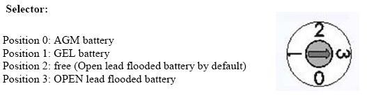
The new battery charger has a selector switch, and each switch selection works with different types of batteries. The selector switch is located under one of the rubber seal plugs found on the DC output side of the battery charger. Remove the rubber seal with a flat screwdriver and make sure the charger is set to the correct switch setting that correlates to the type of batteries used in your vehicle. Note: Position 2 and 3 are the same but use position 3 for flooded batteries. The switch can be changed by using a small flat screwdriver and inserting it into the arrow (center) of the switch.
2 Pin Connector not being
used
The 2-pin male connector on the DC output side of the battery charger does not need to be used. It is intended for vehicle anti-drive. So that at any time the battery charger was plugged into AC voltage the connection between these two wires would become open. If you wish to wire the vehicle with anti-drive one thing to keep in mind is the internal anti-drive switch of the charger cannot exceed 24 volts DC and 10 amps. If power exceeds 24 volts or/and 10 amps the charger will not operate, and replacement of charger will be needed also warranty would be voided. If you wish to setup your vehicle with anti-drive, you can contact e-ride and we can explain some different ways it can be done.
- When charger is not connected neither the battery nor to main supply then relay is idle (contact open)
- When charger is connected to battery: Relay is acting (contact closed)
- When charger is connected to battery and main supply, then relay is idle (contact open)